AC DC Power Supply
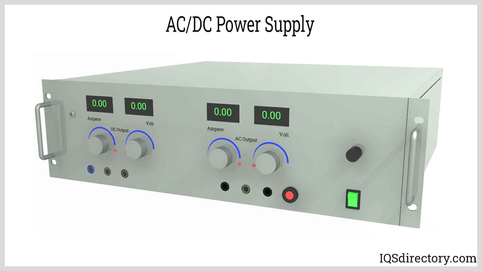
Power supplies are electrical circuits and devices that are designed to convert mains power or electricity from any electric source to specific values of voltage and current for the target device...
Please fill out the following form to submit a Request for Quote to any of the following companies listed on
This article will take an in-depth look at DC/DC power supplies:
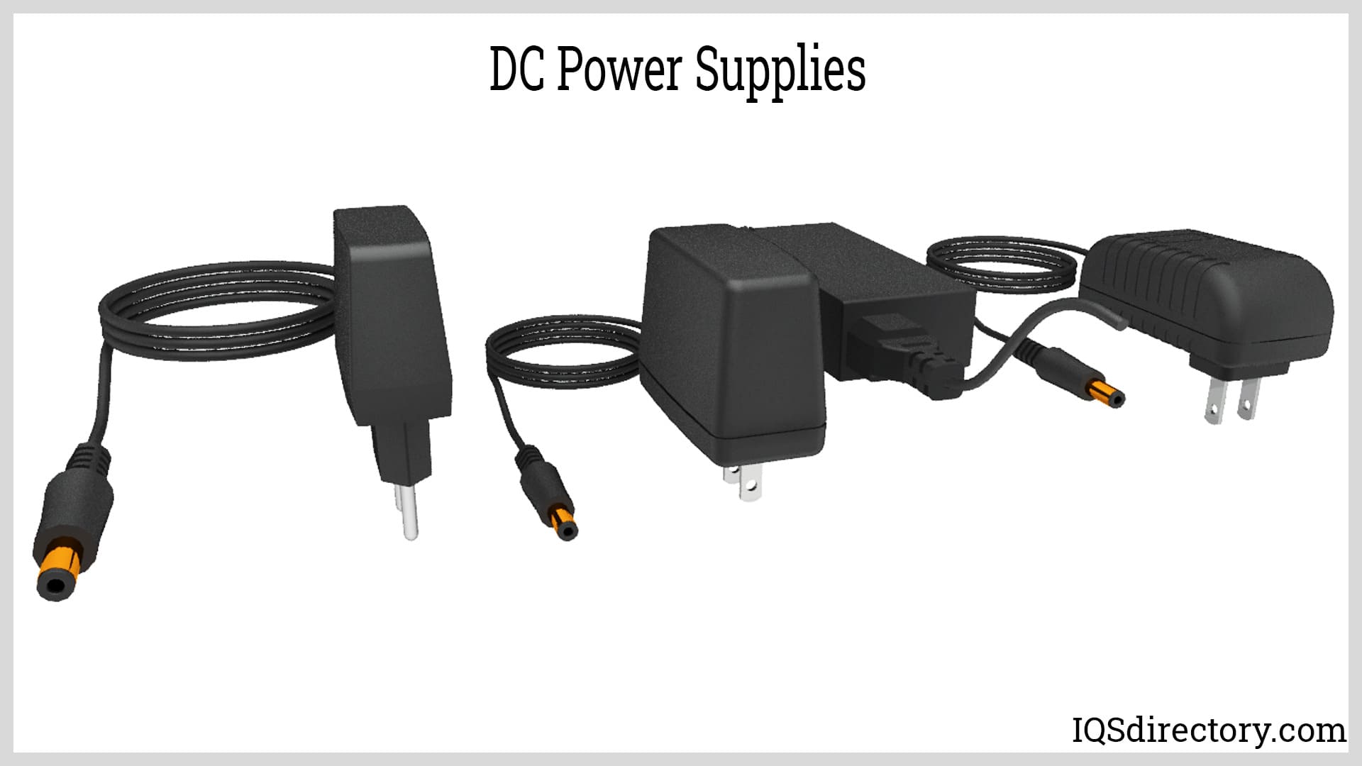
A DC/DC Converter represents a type of power supply utilizing a direct current (DC) voltage input, in contrast to alternating current (AC) voltage. Its main role is to deliver a consistent output voltage that is ideal for powering electronic and electrical equipment. Unlike AC voltage, a DC voltage cannot be modified to higher or lower levels using a transformer.
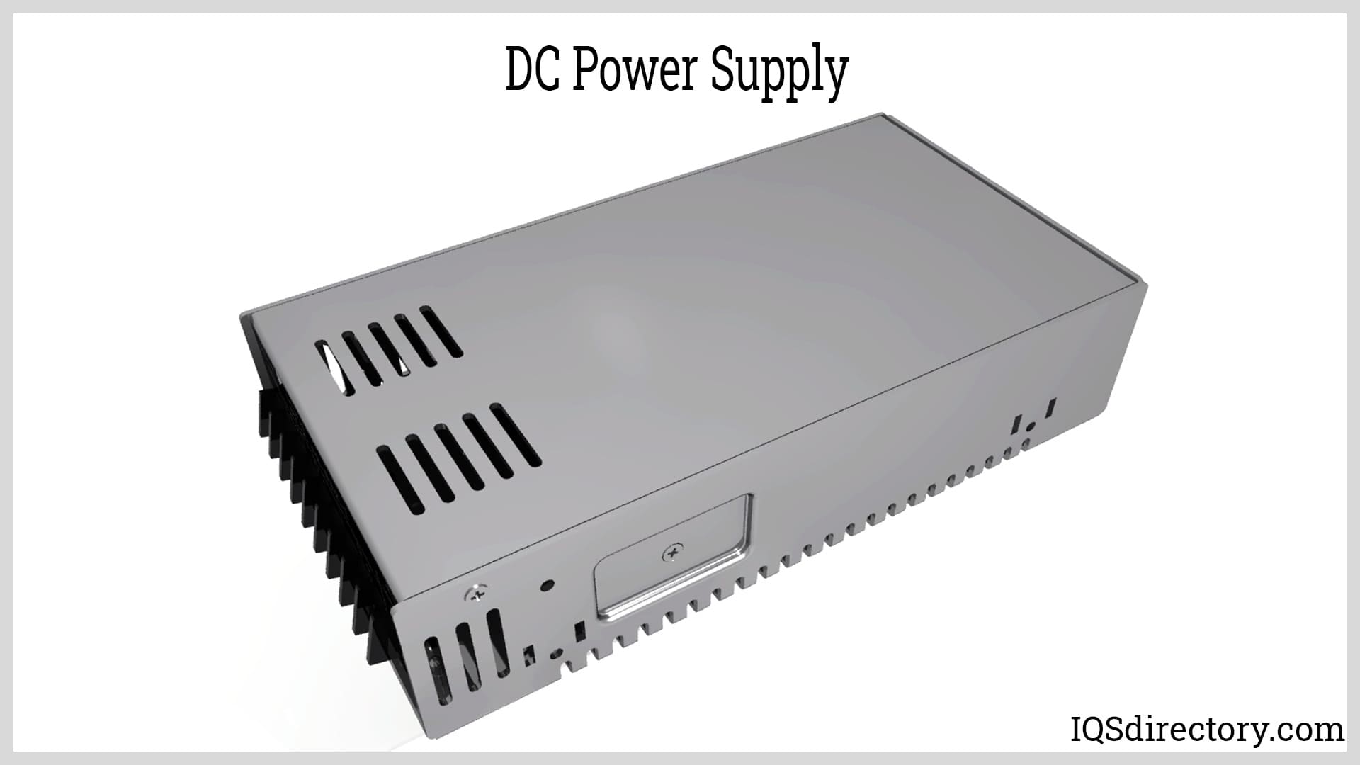
A DC power supply typically has two primary power inputs: alternating current (AC) and direct current (DC). The performance, efficiency, and flexibility of a DC power management subsystem are heavily influenced by the type and quality of power input. Selecting the appropriate input source is essential for ensuring reliable operation and optimizing performance in electronic devices and power systems.
An AC input (alternating current) can be rectified and filtered to produce a regulated DC voltage, which is then fed into a power regulator circuit to generate a stable DC output voltage suitable for sensitive electronics. This process is common in industrial power supplies and consumer electronics where utility AC mains (typically 110V-240V) are converted into required DC voltages. The output from an AC-powered supply can vary—from less than a volt for low-power logic circuits to over 1000 volts for specialized equipment such as electric vehicle charging stations or industrial automation systems. Including advanced power factor correction and EMI filtering can improve input efficiency and meet international electrical standards, further enhancing the subsystem’s performance.
For applications where reliability is critical, such as in medical devices or telecommunications, high-performance AC/DC converters and uninterruptible power supplies (UPS) ensure stable power delivery even during fluctuations in input voltage.
A DC power supply can also accept DC input voltages, most commonly 5V, 12V, 24V, or 48V—standards found in automotive, industrial, and data communication systems. This type of input allows for direct integration with battery systems, renewable energy storage, or distributed power architectures. The output voltage can be precisely controlled to suit the needs of specific devices or circuits, ranging from sub-1V for CPU cores up to hundreds or thousands of volts for power transmission.
Modern DC power management subsystems utilize DC-DC converters such as buck, boost, or buck-boost topologies to step up or step down voltage levels with high efficiency. Applications include server power supplies, electric vehicles, telecommunication infrastructure, and IoT devices that require adaptable and reliable DC input handling. Incorporating overvoltage protection and current limiting features further increases system safety and lifespan.
The DC power management subsystem is typically integrated into the electronic system of portable equipment, where battery power input is crucial for mobility. Portable devices, such as smartphones, laptops, and medical instruments, often include an AC adapter—a power unit that plugs into an AC outlet and provides a regulated DC output voltage both to run the device and recharge its onboard battery. These adapters employ smart charging technology to maximize battery life and ensure safe operation.
When evaluating or selecting a power subsystem, consider the battery chemistry (such as lithium-ion, nickel-metal hydride, or lead-acid) and the charging profile it requires. Advanced battery management systems (BMS) provide functions such as power monitoring, state-of-charge estimation, and thermal management, ensuring optimal performance and user safety.
Energy harvesting technologies enable a DC power subsystem to operate from ultralow voltage inputs generated by renewable sources. Small amounts of energy—from solar power (photovoltaic cells), thermal energy (thermoelectric generators), wind energy (micro-turbines), or kinetic energy (piezoelectric devices and vibration sources)—can be captured and converted by an energy harvesting power converter capable of functioning at millivolt input levels. Once collected, this energy is typically stored in supercapacitors or rechargeable micro-batteries for future use as a reliable secondary power source.
Energy harvesting is essential in wireless sensor networks, healthcare wearables, and remote IoT devices where wired power or frequent battery replacement is impractical. Designing subsystems that efficiently manage and store harvested energy extends operational lifetime and enables new use cases for self-powered electronics.
In summary, understanding the nature of different power inputs—AC, DC, battery, and energy harvesting—is critical when designing and evaluating DC power management subsystems. Matching the input type to your specific application requirements ensures maximum efficiency, reliability, and cost effectiveness. For in-depth guidance on choosing the optimal power supply configuration or to learn more about the latest innovations in power management ICs, contact our technical support team or explore our power management resources.
As covered in the previous chapter, a regulated DC power supply is often derived from a standard AC power source or AC mains supply. Most electrical and electronic circuits—such as those found in computers, industrial automation, and consumer electronics—require a stable, constant DC voltage, regardless of fluctuations in the input voltage or load conditions. While DC batteries can serve as an input source, they are generally costly, require periodic maintenance, and have limited lifespans. As a result, converting an AC input into a reliable DC voltage source, and then regulating it for consistent performance, is essential for supporting sensitive electronic equipment and minimizing the risk of voltage-related device failures. This overall process involves four primary stages and is commonly visualized with a schematic known as the Regulated DC Power Supply Block Diagram. Understanding each stage of this workflow is crucial for engineers, technicians, and system designers evaluating or selecting power supply solutions.
A step-down transformer forms the critical first step in AC-to-DC voltage conversion within a regulated power supply. This transformer converts a high primary AC voltage to a lower, safer secondary voltage suitable for rectification and further processing. It plays a vital role in power management, isolation, and voltage adaptation for different electronic circuits. A step-down transformer typically features two coil windings—primary and secondary—with the primary winding containing more turns than the secondary winding to achieve the desired voltage reduction.
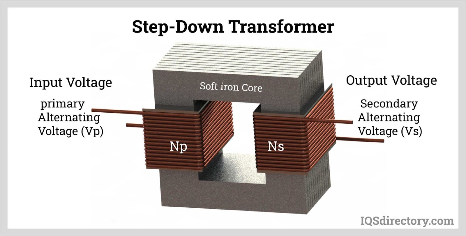
The primary winding is directly connected to the main AC line, ensuring power input, while the secondary winding, although electrically isolated, is electromagnetically linked to the primary. This not only steps down the voltage but also provides galvanic isolation to enhance system safety and reduce the risk of electrical shocks or short circuits.
Step-down transformers used in DC power supply circuits can be classified into three major categories, based on the requirements of the application:
This type of step-down transformer efficiently lowers current and voltage ratings from the AC input, providing a stabilized, reduced voltage output commonly used in low-power devices, adapters, and small-scale electronics.
This transformer type features both a primary and a secondary winding, with the secondary having a center tap. This configuration splits the output voltage at the center tap; for example, a winding configuration delivering ±12V (12V to 0V to -12V) is frequently used in dual-rail DC power supply applications for audio amplifiers or operational amplifier circuits.
A multi-tapped secondary winding offers several voltage options (such as 0-12V, 0-18V, etc.), providing designers the flexibility to select the required output for multiple device types or to enable voltage selection features in laboratory power supplies.
Following transformation, the AC output from the transformer is introduced into the rectifier circuit for conversion into DC.
The second stage of regulated DC power supply functionality is rectification, which converts AC voltage into a unidirectional (DC) voltage. This process is performed by rectifiers, which are electronic circuits constructed primarily with diodes—a fundamental component in power electronics and energy conversion systems.
Rectifiers are broadly divided into controlled rectifiers (using SCRs, also known as Silicon Controlled Rectifiers, or thyristors, for adjustable or variable output voltage) and uncontrolled rectifiers (using standard diodes for fixed voltage applications). The choice depends on whether variable output or fixed DC output is needed.
There are two basic rectifier circuit types: half-wave rectifiers and full-wave rectifiers, each with its benefits and limitations regarding output quality and efficiency. Understanding these is key to proper regulated power supply design and troubleshooting.
A half-wave rectifier circuit employs a single diode, converting only one half of the AC input waveform to a pulsating DC output—discarding the other half. Typically, there are:
For industrial or high-power applications, three-phase rectification (polyphase rectification) is often utilized, efficiently combining three single-phase rectifiers. This setup is preferred when a single-phase rectifier cannot supply adequate power to meet the needs of heavy-duty machinery or facility-wide DC bus systems.
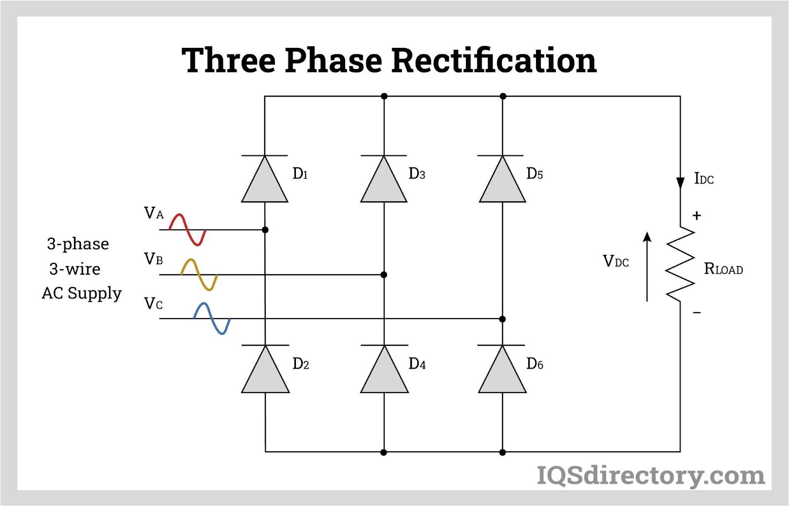
Multi-phase rectifier circuits, such as 12-pulse configurations, help minimize harmonic distortion and improve power factor by staggering current pulses. These advanced rectifier systems, often found in commercial DC power supplies and high-performance regulated power sources, make use of series-connected 6-pulse rectifiers with a total of 12 diodes feeding a unified DC bus. This approach effectively cancels the 5th and 7th harmonic currents, leaving the 11th harmonic as the largest. Maintaining low harmonic levels is critical for protecting sensitive loads and meeting regulatory standards for electromagnetic compatibility (EMC).
Extensions to this topology, such as 18-pulse rectifiers (using three sets of 6-pulse rectifiers), provide even greater harmonic mitigation but at higher cost and increased space requirements. These systems are typically specified in demanding industrial or laboratory environments where ultra-clean DC power is required.
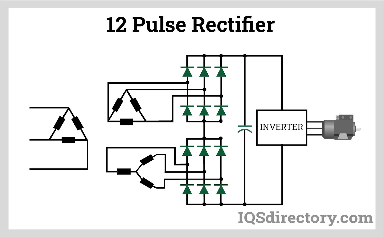
Full-wave rectification uses multiple diodes to convert both positive and negative half-cycles of the AC signal into a continuous DC output—significantly improving efficiency and output voltage stability compared to half-wave rectification. Two main full-wave rectifier circuits are widely used in regulated DC power supply units:
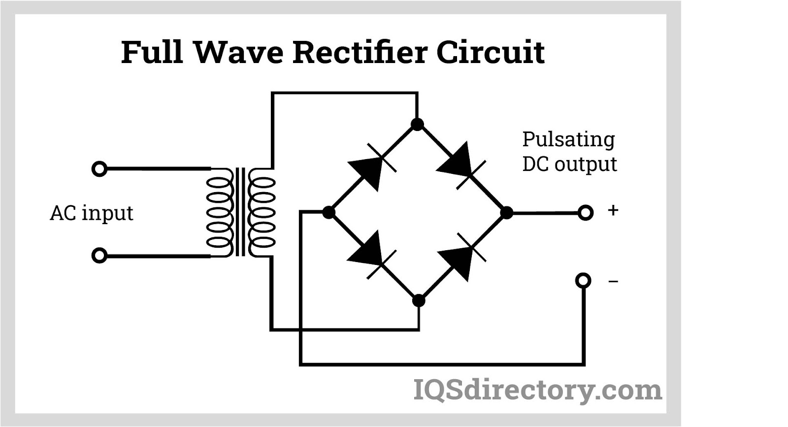
After rectification, a key challenge remains: the so-called "ripple voltage"—a residual AC component superimposed on the DC output. To refine and stabilize the DC signal for sensitive electronic loads, a filtration stage is required. DC filtration utilizes filter circuits such as capacitor filters, LC (inductor-capacitor) filters, choke input filters, and π-type filters, all designed to smooth out ripples and deliver cleaner DC voltage.
In a basic capacitor filter, the capacitor charges during voltage peaks and discharges as voltage drops, helping maintain a steady voltage output. For applications demanding even tighter voltage regulation and lower noise—for example, laboratory power supplies, RF systems, or precision instrumentation—more advanced filter designs, such as LC or π-filters, are used to achieve the lowest possible ripple and highest DC purity. Effective DC filtration is essential to protect microcontrollers, integrated circuits, and other sensitive electronic components from signal noise or voltage fluctuations.
The final and most critical step in regulated DC power supply operation is voltage regulation. After AC-DC conversion and filtration, the output voltage can still be subject to minor fluctuations due to changes in line voltage (mains variation), load current, or ambient temperature shifts. Voltage regulators are electronic devices or integrated circuits engineered to keep the DC output voltage steady within a precise range, regardless of these external variations.
Several types of regulators are commonly used to achieve accurate and stable DC output:
In advanced power supply designs, you may also find switching regulators (buck converters, boost converters) which provide high efficiency, especially in larger or portable electronic devices. Linear regulators, on the other hand, are favored for low noise performance and simplicity in sensitive analog circuitry.
Ultimately, a regulated DC power supply block diagram helps illustrate the complete chain of energy conversion—from AC input through transformation, rectification, filtration, and stabilization—ensuring a clean, predictable DC source. By understanding each block and its role, engineers can better select, design, or troubleshoot DC power supplies for high reliability and optimal performance in their electronic systems.
A DC power supply converts input voltage—either AC or DC—into a consistent, regulated DC output voltage optimized for electronic and electrical equipment.
The type and quality of AC, DC, battery, or energy harvesting inputs directly impact subsystem efficiency, reliability, flexibility, and application suitability in DC power management.
The key stages are step-down transformation, rectification, filtration, and voltage regulation—transforming AC input into stable DC for sensitive electronics.
Ripple voltage is minimized using filter circuits such as capacitors, LC filters, choke input filters, and π-type filters to smooth and stabilize the DC output.
Buck, boost, and buck-boost converters are widely used for stepping voltage up or down with high efficiency in modern DC power management applications.
Energy harvesting allows DC subsystems to operate from ultralow voltage inputs using sources like solar, thermal, wind, or kinetic energy, enabling long-term, maintenance-free operation of remote electronics.
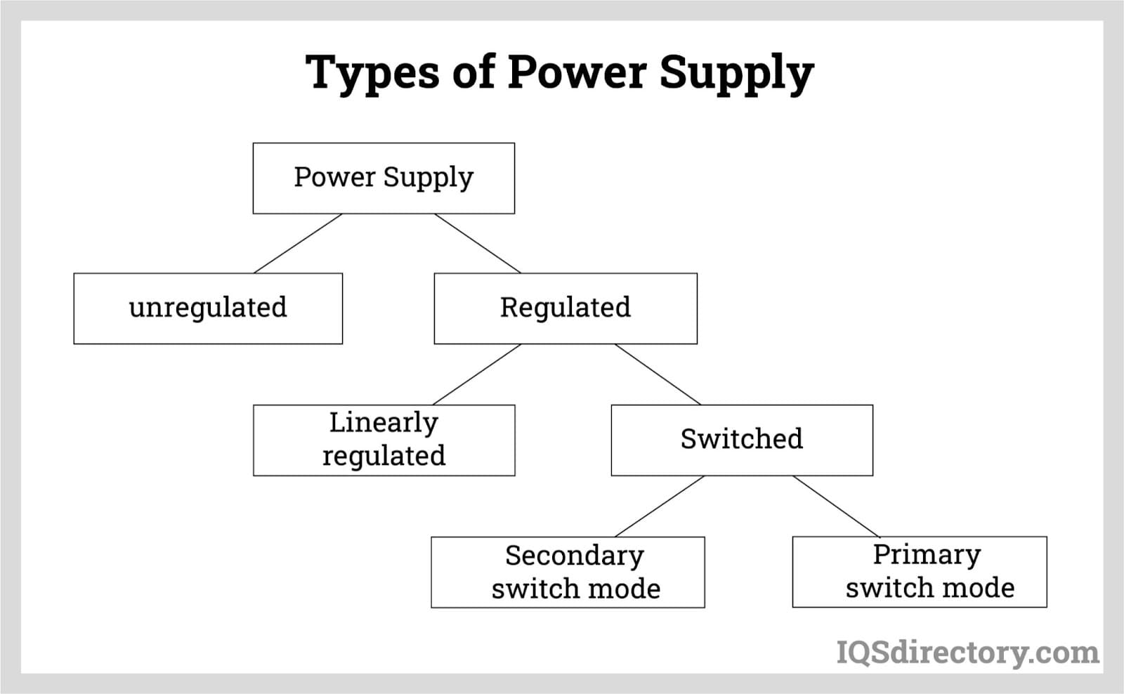
Regulated power supplies and unregulated power supplies are the major classifications of DC power supplies. Regulated power supplies are subdivided into two types: linearly regulated and switch mode. Switch-mode power supplies can be primary or secondary switch mode.

The following list describes each type and design of DC power supply.
An unregulated power supply uses the AC mainline as its input. The AC voltage first passes through a step-down transformer, which reduces the voltage. This lower secondary voltage is then rectified and converted into DC. The output voltage from the rectifier is smoothed by a capacitor. As the name implies, unregulated power supplies lack a regulator, meaning any fluctuations in the mainline directly affect the output voltage.
Unregulated power supplies feature a simple design, which contributes to their durability and results in a typical efficiency of around 80%.
They are primarily used in electromechanical applications that do not require precise output voltages, such as supplying power to contactors.
Linearly regulated power supplies use the AC-DC conversion process described in Chapter 3.
The AC mains voltage is first stepped down to a lower level using a transformer, then rectified and filtered. The final step involves regulating the smoothed DC voltage, typically with a power transistor, to maintain a constant output.
In linearly regulated power supplies, the power transistor functions as a variable resistor.
Energy losses occur as the current passes through the power transistor, with the lost energy being dissipated as heat. Therefore, proper ventilation is necessary for the power supply.
Due to these energy losses, linearly regulated power supplies generally have an efficiency of about 50%.
For applications requiring very precise output voltage, such as highly accurate medical devices, linearly regulated power supplies are often used.
Primary switch mode power supplies start with rectifying the AC mains, followed by filtering and chopping/switching processes.
Chopping a DC voltage involves periodically switching it at a frequency of 40-200 kHz using a power transistor.
Unlike in linearly regulated power supplies, where power transistors act as variable resistors, in primary switch mode power supplies, they function as switches.
During the chopping/switching phase, a square-wave AC voltage is generated, which is then fed into a high-frequency transformer in the secondary circuit. The voltage is subsequently rectified and smoothed again.
The chopping rate can be adjusted based on the load to control the amount of energy transferred to the secondary circuit.
Because high-frequency AC voltage is used, transformers in primary switch mode power supplies can be smaller compared to those needed for low-frequency transformations.
These power supplies can handle a wide range of input voltages, including DC, as the input voltage does not directly impact the output voltage.
A short-time buffer of up to 200 ms can be included to handle mains voltage interruptions. However, the buffering time is limited by the size of the capacitor.
While a larger capacitor allows for longer buffering times, it is not ideal for small power supplies. Therefore, the power supply should be optimized to balance buffering time and capacitor size.
Primary switch mode power supplies are commonly used in both electronics and electromechanical applications.
Secondary switch mode power supplies are similar to primary switch mode power supplies, but the chopping occurs on the secondary side.
As a result, a larger transformer is needed to convert the 50/60 Hz mains voltage.
However, mains pollution is reduced since the transformer also functions as a filter.
In industrial applications, the primary switch mode power supply is the most commonly used type due to its wide input voltage range, high efficiency, and compact size.
DC/DC power supplies are integral to many products, as electronic devices typically use DC power. This includes portable electronics like laptop computers and mobile phones, which are powered by batteries. These devices often contain multiple small circuits, each with specific voltage requirements that may differ from the battery or external supply voltage, which is frequently either higher or lower. Larger DC/DC power supplies are also used to optimize power output from photovoltaic systems and to charge batteries. Many DC/DC power supplies, such as those used for LEDs, are designed to regulate the voltage output.
When selecting a power supply for new engineering applications or upgrading existing installations, key factors to consider include efficiency, regulation time, weight and size, residual ripple, cost, and application fields.
A DC-DC converter is a type of power supply that uses DC voltage as its input. Its primary function is to provide a regulated output voltage for various electrical and electronic applications. Unlike AC voltage, which can be altered using a transformer, DC voltage cannot be changed between different levels using a transformer. Instead, a DC-DC converter serves this purpose, functioning similarly to a transformer.
Much like transformers, DC-DC converters adjust the input energy to a different impedance level. The converter itself does not generate energy; all output power is derived from the input power. However, in practical applications, some energy is lost within the converter due to component inefficiencies. Thanks to advances in components and circuit design, modern DC-DC converters can achieve efficiencies of up to 90%.
DC/DC power supplies can be found in either non-isolated or isolated configurations. In isolated converters, the output and input circuits are galvanically isolated, meaning there is no direct DC path between them. This isolation is crucial for separating the output and input circuitry to ensure safety from dangerous voltages or to reduce electrical noise. Isolated converters can also provide multiple output voltages from a single unit.
Non-isolated converters, on the other hand, have a direct DC connection between the output and input through a common ground. These converters are generally smaller and less expensive than isolated ones. Non-isolated converters can also produce a negative voltage output from a positive voltage input.
This type of DC-DC converter is used for stepping up or down the voltage by a small ratio (less than 4:1).
Non-isolating converters do not provide dielectric isolation between the input and output.
Examples of such converters include 24V/12V voltage reducers, 5V/3V reducers, and 1.5V/5V step-up converters.
DC-DC converters are useful in the following applications:
DC power supplies have four basic outputs or modes: constant voltage, constant current, voltage limit, and current limit. They can be designed with various combinations of these outputs to suit different applications.
The circuit includes a control element in series with a rectifier and load device, a configuration used in linear power supplies. The main advantages of series regulation are:
Adding a pre-regulator to a series regulator enables circuit techniques suitable for medium and high-power design applications. Pre-regulation also enhances efficiency by 10-20% by reducing power dissipation in the series regulating components. The main advantages of series regulation with pre-regulation are:
Switching regulation in a basic switching supply involves a series of transistors functioning as open and closed switches. The main advantages of switching regulation are:
This regulating technique is used in high-power applications. The main advantages of SCR are:
Like the constant voltage power supply, but it has less precise regulation characteristics.
Like the constant current power supply, but it has less precise regulation characteristics.
There are several types of DC/DC converters available, including buck, boost, non-inverting buck-boost, and flyback converters. Buck converters produce a lower output voltage than the input voltage, while boost converters provide an output voltage higher than the input. Buck-boost converters can deliver an output voltage that is either above or below the input voltage, making them ideal for battery-powered applications where extended battery life is critical.
Flyback converters are used for lower power applications, typically below 100 W. They operate by storing energy in the magnetic component of a power supply when the power switch is ON and delivering it to the output when the switch is OFF. Flyback converters also offer isolation between the input and output voltages, which is useful for polarity inversion and reducing system noise.
These four types of converters are the most commonly used. The choice of which to use depends on factors such as size, performance, cost, and specific application requirements.
The advancement of integrated circuits with sophisticated features allows power supplies to operate at higher switching frequencies. This capability enables designers to reduce the size of magnetic components, such as transformers and output filter inductors, in switching power supplies.
Higher switching frequencies facilitate the rapid replenishment of a capacitor’s charge, allowing the use of smaller and fewer output capacitors while achieving fast and precise dynamic output performance. The commercialization of wide band gap power semiconductors, such as silicon carbide (SiC) and GaN transistors, supports higher switching frequencies with lower switching losses. This development enables power supply designers to achieve higher power densities compared to those possible with Silicon MOSFETs.
A power supply includes a switching system that divides a constant power source into controllable increments of energy. This is followed by a filtering system that converts these increments back into a steady, usable output power. In its simplest form, a non-isolated power supply consists of a switching transistor, a diode, an inductor, and an output capacitor. Various topologies can be created using these four circuit elements along with the necessary control circuitry to achieve the desired output voltage and efficiency.
In most applications, power is distributed at higher voltage levels to maximize system efficiency. The role of the power converter is to step down the incoming voltage to a lower value required by the load. Power converters that provide an output voltage lower than the input voltage are known as buck converters.
When the switch (SW) is closed or ON, energy is transferred from Vin to the load. By adjusting the ON and OFF times, the amount of energy delivered to the output can be controlled. The ratio of the ON time to the total cycle time (ON time plus OFF time) defines the duty cycle of the power converter, which ranges from 0 to 1. The output voltage can be varied from 0 V to nearly Vin by adjusting the SW ON-time.
In a buck converter, the inductor is connected directly to the output capacitor and load. The inductor current continuously flows through the diode to the output even when the switch is open, thanks to the antiparallel connected diode. For regulated output converters, the duty cycle is controlled by the power supply controller to maintain a constant output voltage despite variations in Vin or system parameters. Non-isolated buck converters can achieve efficiencies of up to 98%.
Boost converters use the same circuit elements as buck converters but arranged differently to achieve distinct performance characteristics. Boost converters increase the input voltage to provide an output voltage greater than the input voltage. In a boost converter, power is transmitted to the output through a two-step process, with the inductor serving as a temporary storage element. When the switch (SW) is closed, current flows into the inductor, and the longer the switch remains ON, the more magnetic energy is stored.
The diode prevents current from flowing back from the load, while the output capacitor maintains the output voltage. When the switch is opened, the energy stored in the inductor's magnetic field flows through the diode, recharges the capacitor, and replenishes the energy delivered to the load when the switch is ON. This two-step process can result in high peak currents in components and affects efficiency in higher power applications, limiting its use to lower power applications.
Buck-boost converters are hybrid combinations of buck and boost power converters. They integrate buck circuits on the input side and boost circuits on the output side, sharing a common inductor. This topology allows the converter to regulate the output voltage regardless of whether the input voltage is above or below the desired output voltage. The output voltage remains steady as the battery transitions from a fully charged state to a fully discharged state.
These converters are particularly popular in battery-powered applications, where maintaining a consistent output voltage is crucial even as the battery discharges to its lowest operational limit. This approach extends the runtime of battery-powered devices and ensures consistent performance throughout battery discharge.
When the input voltage (Vin) is higher than the output voltage (Vout), such as 14.5V in a fully charged 12V battery system, the circuit operates in buck mode with the boost switch (SW2) open and output Diode-2 continuously conducting. As the input voltage drops below the set Vout level during battery discharge, the input switch (SW1) remains ON, and the circuit functions as a boost converter with SW2 active to maintain the output voltage. A single control circuit manages the output voltage and determines whether buck or boost mode is needed.
A synchronous rectifier functions similarly to a diode, allowing current to pass in one direction. When traditional power diodes are used as freewheeling or rectifying diodes, the conduction losses can be excessively high, particularly at high currents where the forward voltage (VF) is approximately 0.6 to 0.7 volts.
To reduce these losses, power MOSFETs are used instead of rectifier diodes and freewheeling diodes. This approach significantly improves power efficiency compared to standard diodes or even Schottky diodes. However, driving the power MOSFETs synchronously with the main power switches can be complex and requires specialized controllers. Despite this complexity and cost, the benefits of using synchronous rectifiers make them a popular choice in all types of switching power supplies.
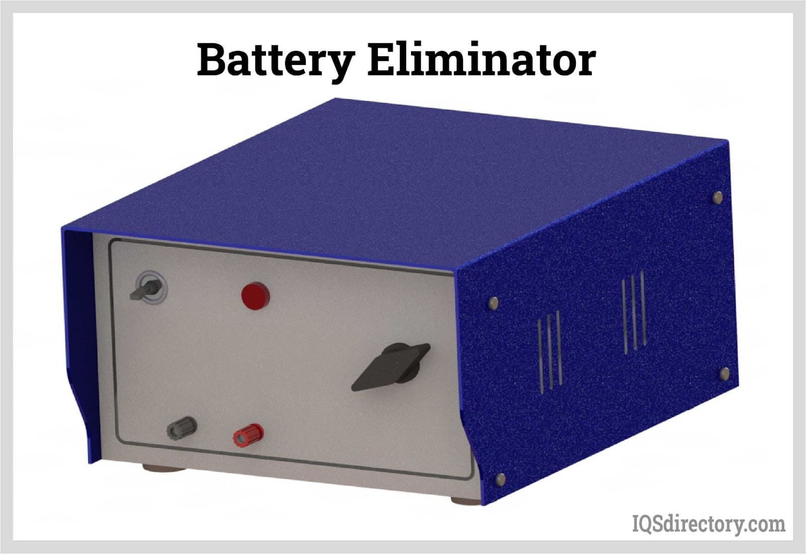
Battery eliminators are affordable, compact DC power supplies designed to replace batteries when they are not available. They are commonly used with battery-operated equipment and can provide 18V DC power to devices typically powered by automobile batteries, such as CB radios and automotive stereo systems.
Battery eliminators come equipped with an ON/OFF switch and a rotary switch to select the desired output DC voltage. Available in output voltages ranging from 1.5V to 12V, with increments of 1.5V, these units can be operated continuously and safely even in a dead short.
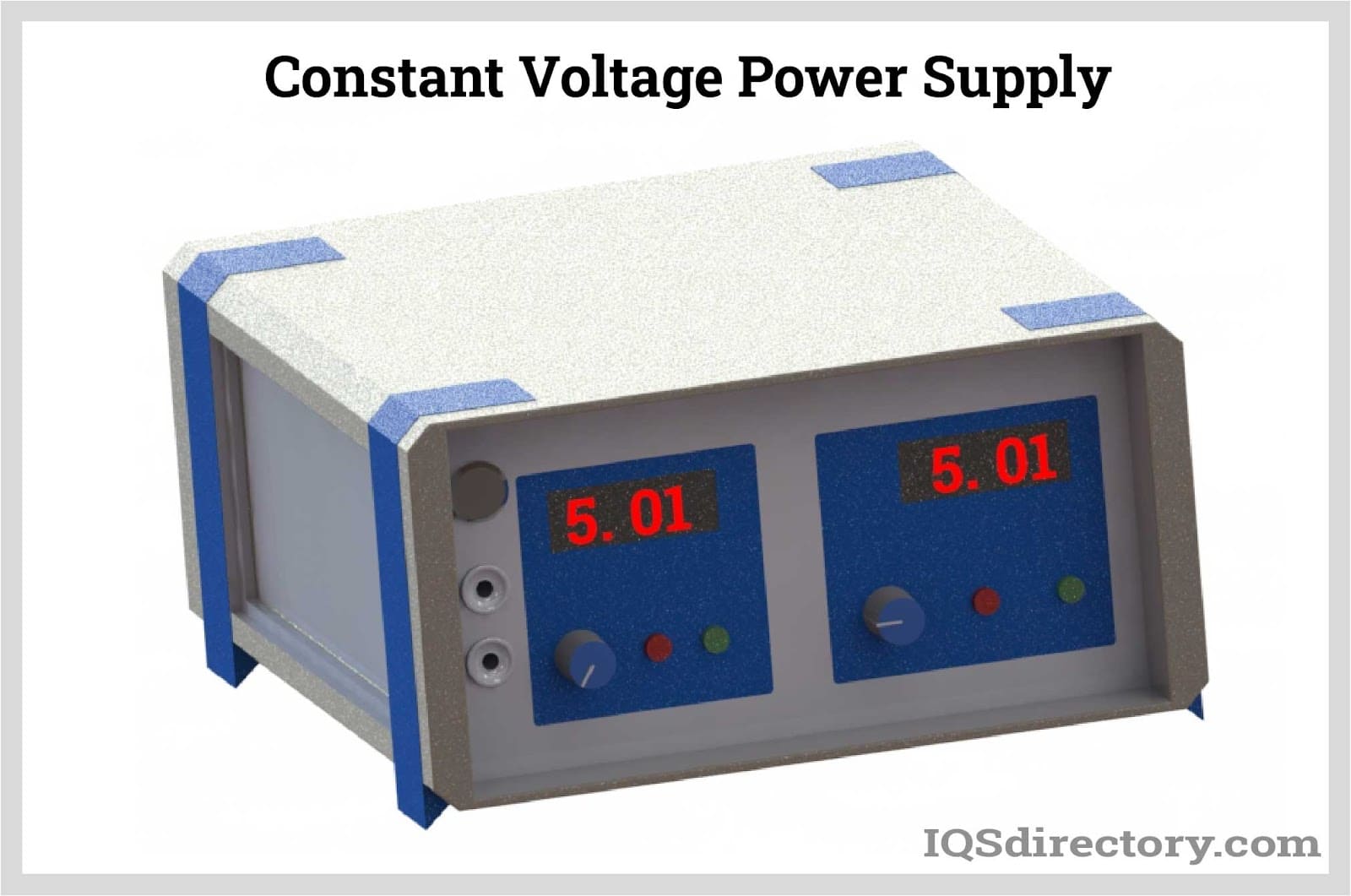
A constant voltage supply delivers a steady and adjustable voltage and features a more complex design compared to battery eliminators. These supplies include voltage and current meters, allowing users to monitor both the voltage and current values. The output voltage can be adjusted using a knob, though some units may not be adjustable down to zero volts.
In some models, the rated current may not be available at all output voltages. In such cases, the maximum output current is proportional to the output voltage. Additionally, tie points with a current limit may be provided to connect an external digital meter for precise voltage monitoring or to other circuits.
A constant voltage/constant current supply maintains both a constant voltage and a constant current. In constant current mode, the supply keeps the current steady regardless of the load's resistance. Typical units feature fine and coarse adjustable controls for both voltage and current. Some models use 10-turn pots, thumbwheel switches, or pushbutton switches for adjustments, eliminating the need for a meter when using thumbwheel and pushbutton switches.
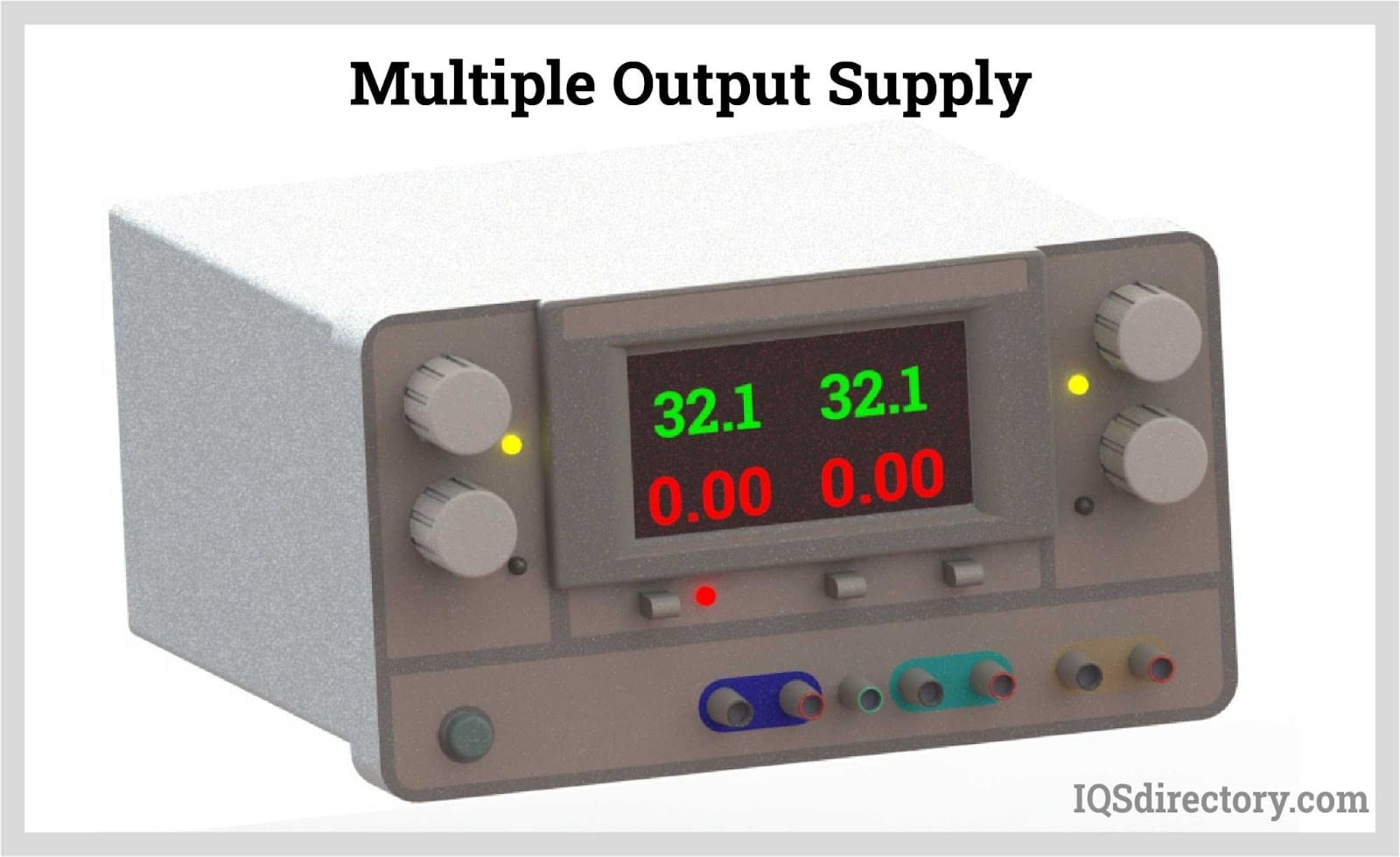
Multiple output DC power supplies offer more than one DC output, making them a cost-effective choice for systems that require multiple voltages.
For instance, a triple output supply is commonly used in circuit development:
With a multiple output supply, you can set each of the three outputs independently using a knob or keypad. Outputs can be turned ON and OFF either separately or all at once, enabling the entire printed circuit board to be powered simultaneously.
A typical unit also includes features such as:
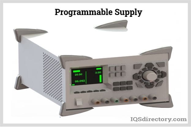
A programmable supply, known as system power supplies, are integrated into a computer operated system during production or testing.
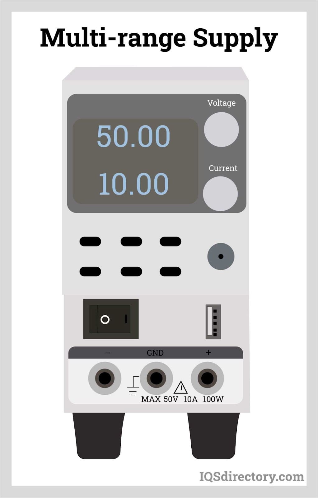
A multi-range DC power supply supports various combinations of voltage and current while still delivering maximum power. Unlike conventional power supplies, which provide maximum output power only at specific fixed voltage and current ratings, a multi-range supply maintains high output power across different voltage and current combinations.
The main advantages of a multi-range supply include:
When selecting a DC power supply, consider the following specifications:
DC power supplies that offer both constant current and constant voltage modes are versatile and suitable for most applications.
Another important specification to consider is the power supply output. Typically, it is advisable to choose a DC power supply with an output rating higher than the current requirement, as most projects tend to incorporate additional functionalities later in the design cycle.
Regulation refers to either load regulation or line regulation. Load regulation, typically ranging from 0.1% to 0.01%, measures the change in output voltage as the load varies. Line regulation, also usually between 0.1% and 0.01%, measures the change in output voltage in response to fluctuations in the input AC voltage.
Most components of a DC power supply are sensitive to temperature. Therefore, it is important to check the operating temperature range and the temperature coefficient of the power supply. Ideally, a lab-quality power supply should have a temperature coefficient of 0.05% /°C.
Three-phase power is commonly used in larger power supplies, offering greater efficiency compared to single-phase power supplies and providing a higher ripple frequency.
Additional specifications to consider include ripple and noise, tracking accuracy, and DC isolation.

Power supplies are electrical circuits and devices that are designed to convert mains power or electricity from any electric source to specific values of voltage and current for the target device...
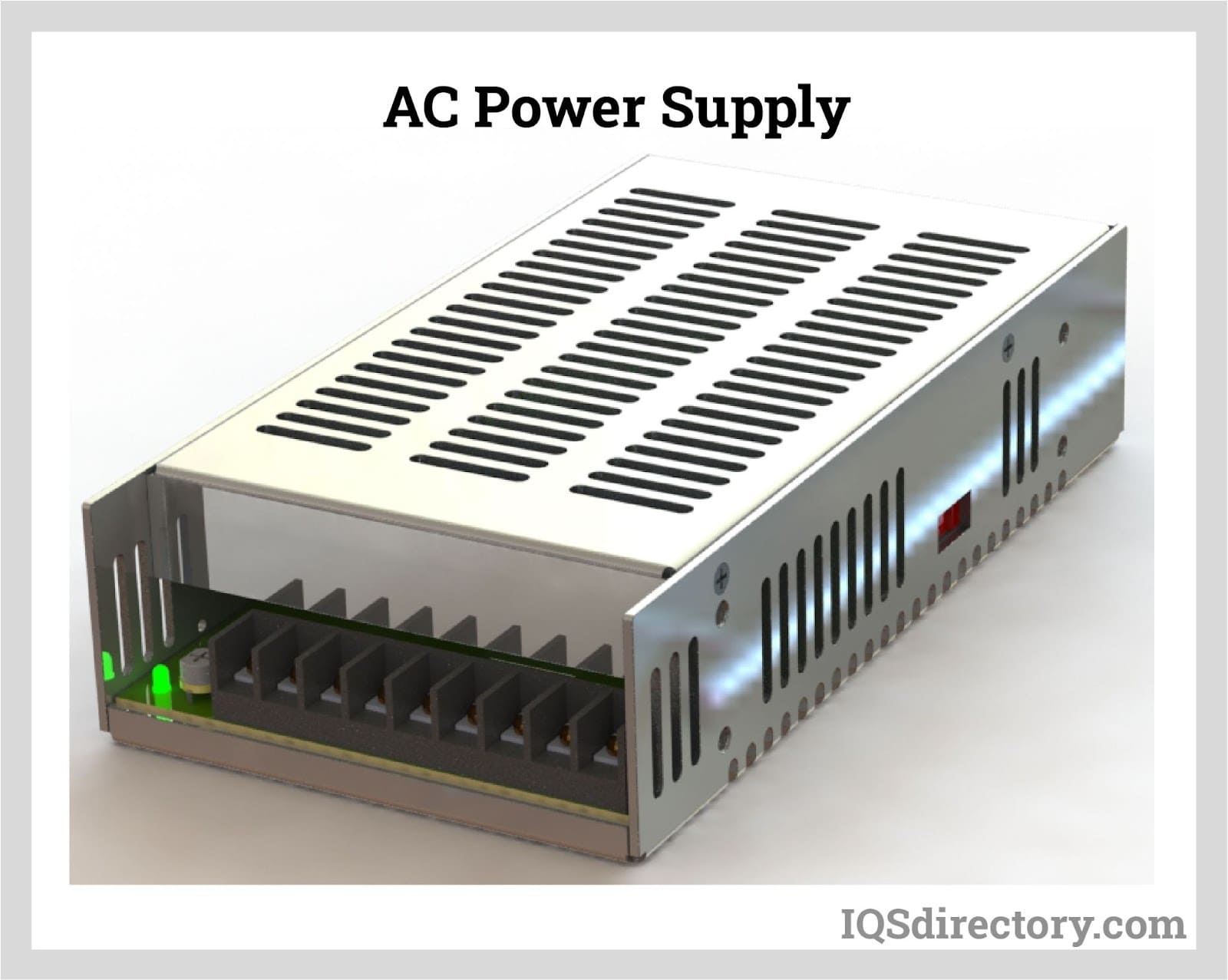
An AC power supply is a type of power supply used to supply alternating current (AC) power to a load. The power input may be in an AC or DC form. The power supplied from wall outlets (mains supply) and...
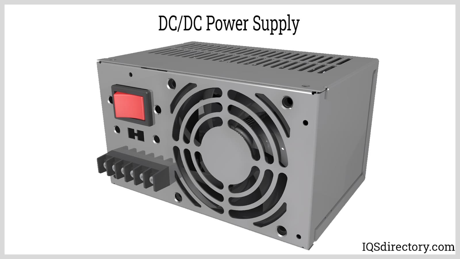
A DC DC power supply (also known as DC DC Converter) is a kind of DC power supply that uses DC voltage as input instead of AC/DC power supplies that rely on AC mains supply voltage as an input...
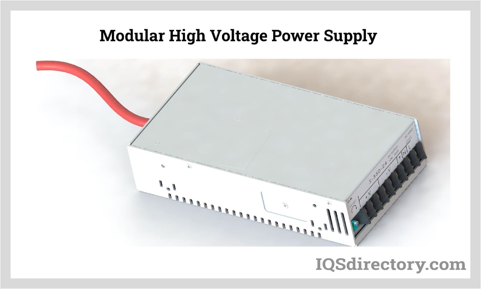
By definition a power supply is a device that is designed to supply electric power to an electrical load. An electrical load refers to an electrical device that uses up electric power. Such a device can be anything from...
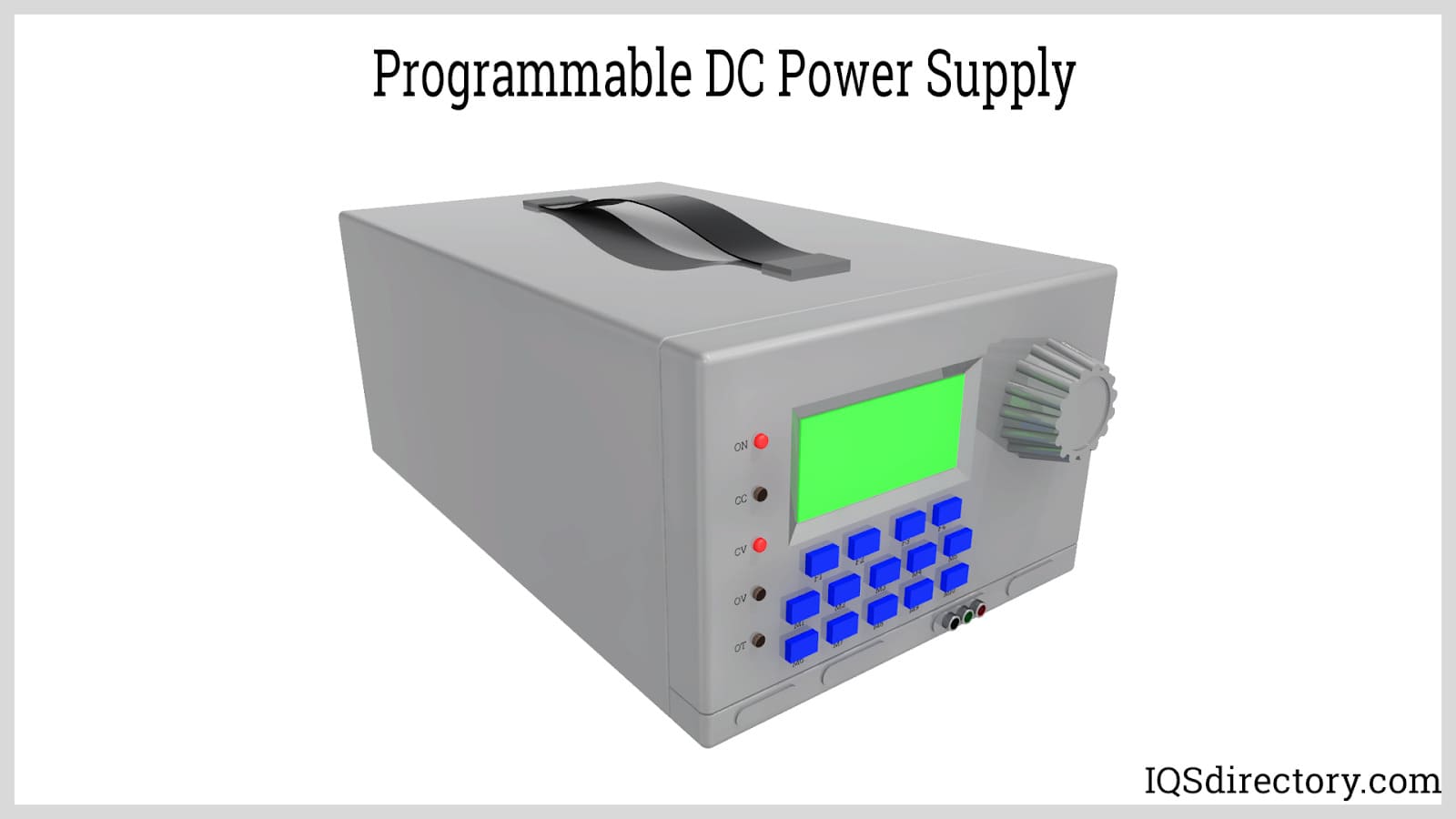
A programmable power supply is a method for controlling output voltage using an analog or digitally controlled signal using a keypad or rotary switch from the front panel of the power supply...
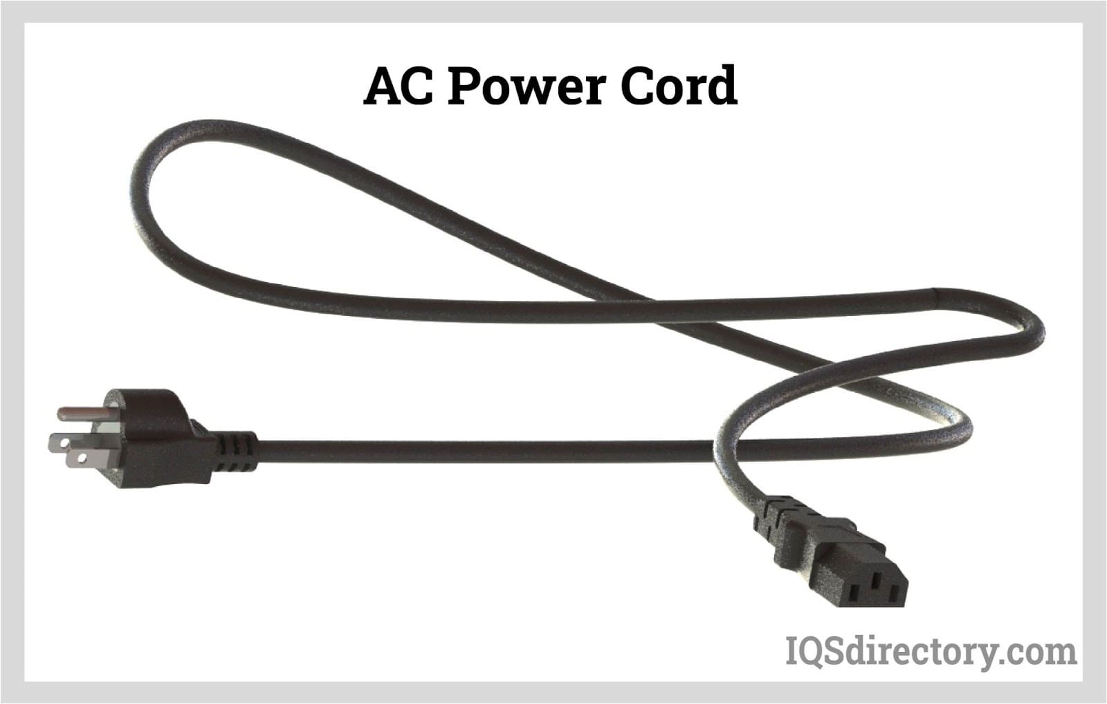
An AC power cord is a detachable way of providing an alternating current of electric energy from a mains power supply to an electrical appliance or equipment. Serving industries like...
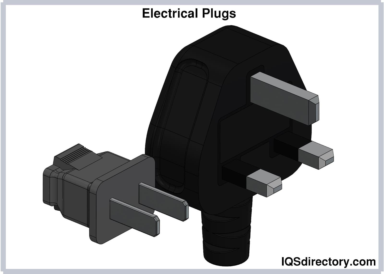
Electrical plugs, commonly known as power plugs, are devices responsible for supplying and drawing current from a receptacle to the circuitry of an electrical appliance...
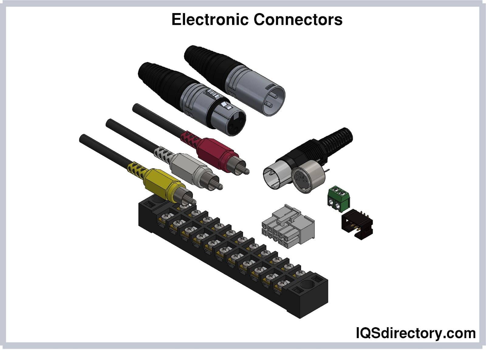
Electronic connectors are devices that join electronic circuits. They are used in assembling, installing, and supplying power to electrical devices. Connectors are an important component of every electronic equipment used in...
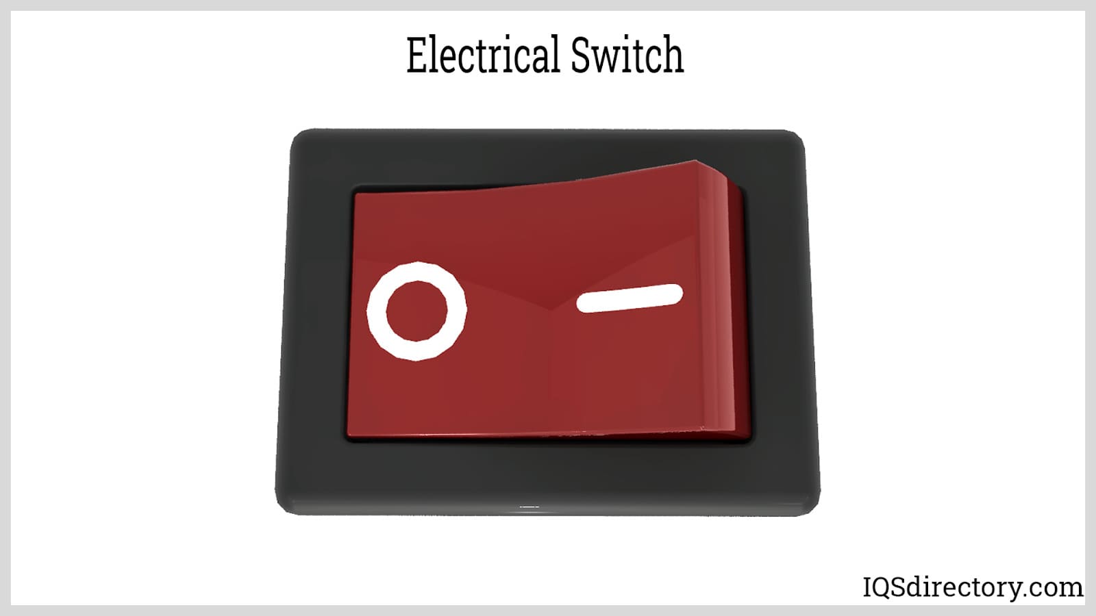
An electric switch is a device – usually electromechanical – that is used to open and close an electric circuit. This disables and enables the flow of electric current, respectively...
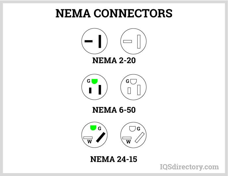
A NEMA connector is a method for connecting electronic devices to power outlets. They can carry alternating current (AC) or direct current (DC). AC current is the typical current found in homes, offices, stores, or businesses...
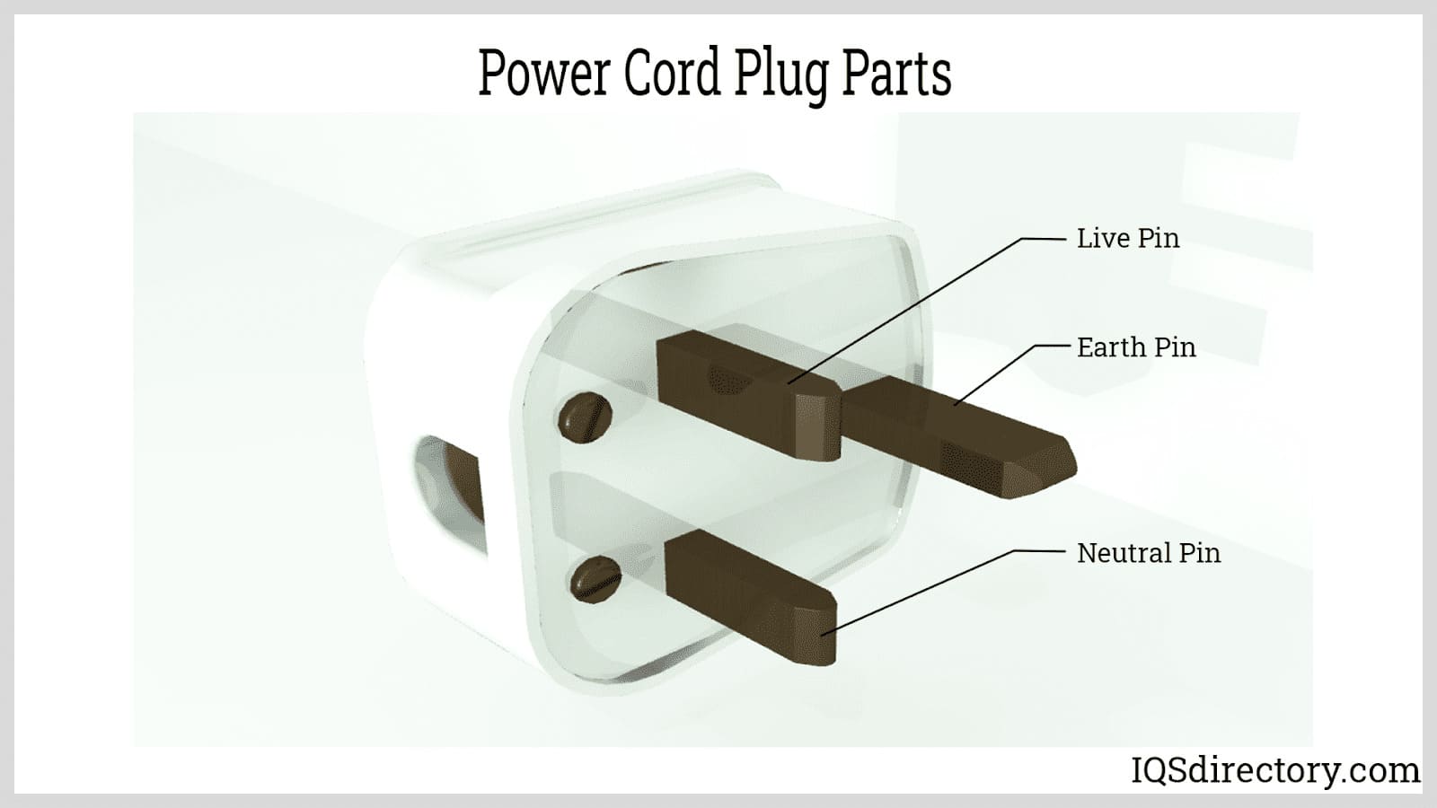
A power cord is an electrical component used for connecting appliances to an electrical utility or power supply. It is made from an insulated electrical cable with one or both ends molded with connectors...
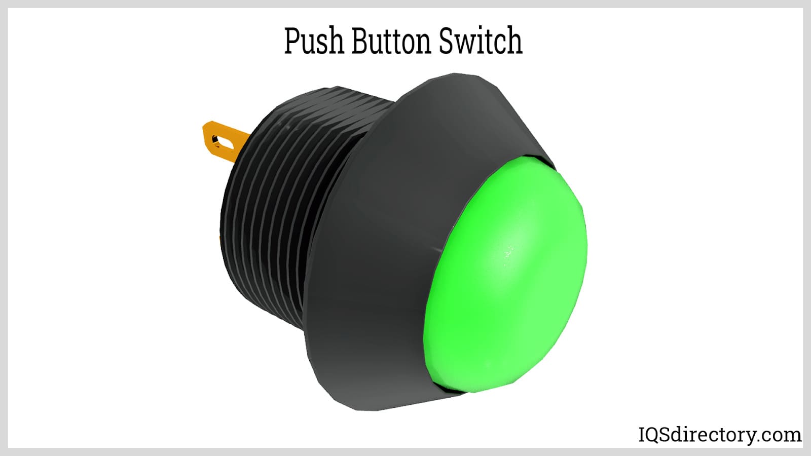
Push button switches are electrical actuators that, when pressed, either close or open the electrical circuits to which they are attached. They are capable of controlling a wide range of electronic gadgets...
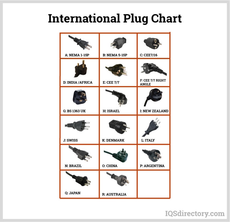
Thomas Edison developed the power distribution system in 1882. He wrapped a copper rod in jute, a soft shiny fiber from plants, as an insulator. The jute wrapped copper rod was placed in a pipe with a bituminous compound...