Electric Switches
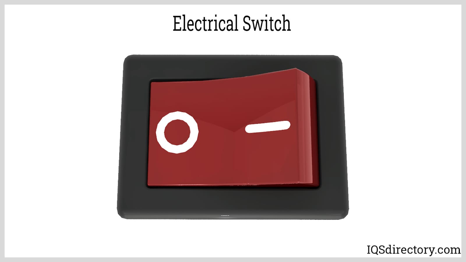
An electric switch is a device – usually electromechanical – that is used to open and close an electric circuit. This disables and enables the flow of electric current, respectively...
Please fill out the following form to submit a Request for Quote to any of the following companies listed on
This article will take an in-depth look at push button switches.
The article will bring more detail on topics such as:
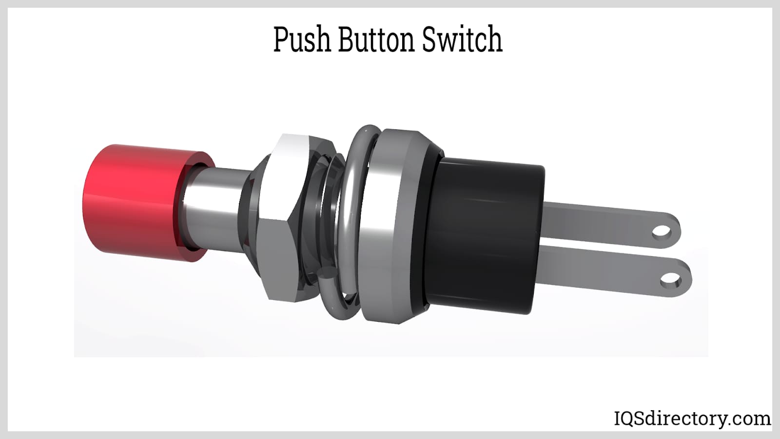
In this chapter, we delve into the roles and mechanics of push button switches.
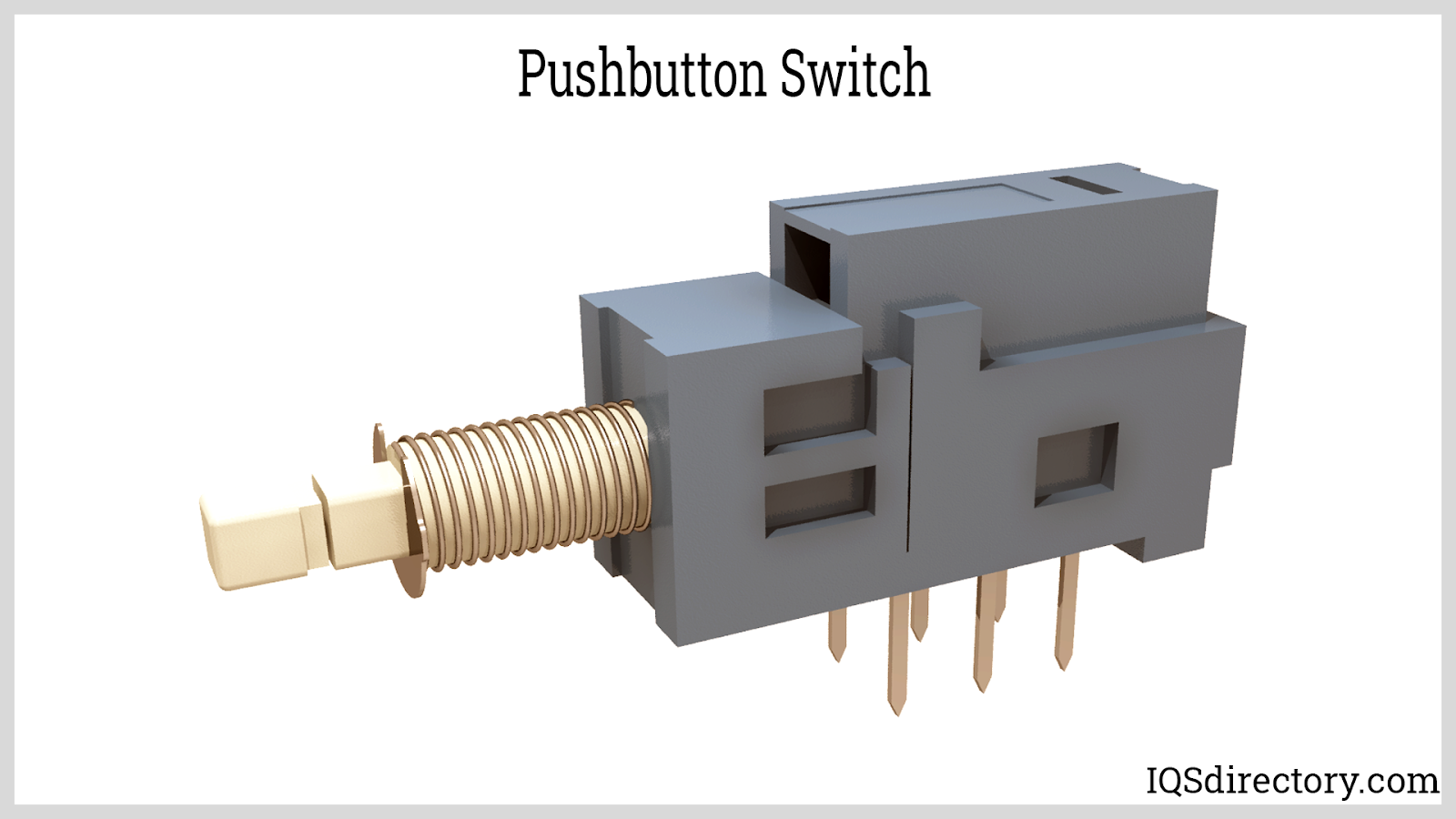
Push button switches, also referred to as pushbutton switches, are devices that can create or break circuit connections upon being pressed. They are widely used for managing a plethora of electronic systems and devices.
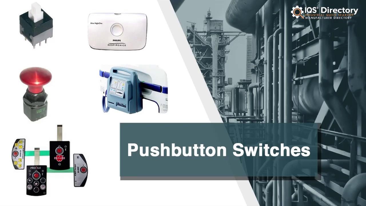
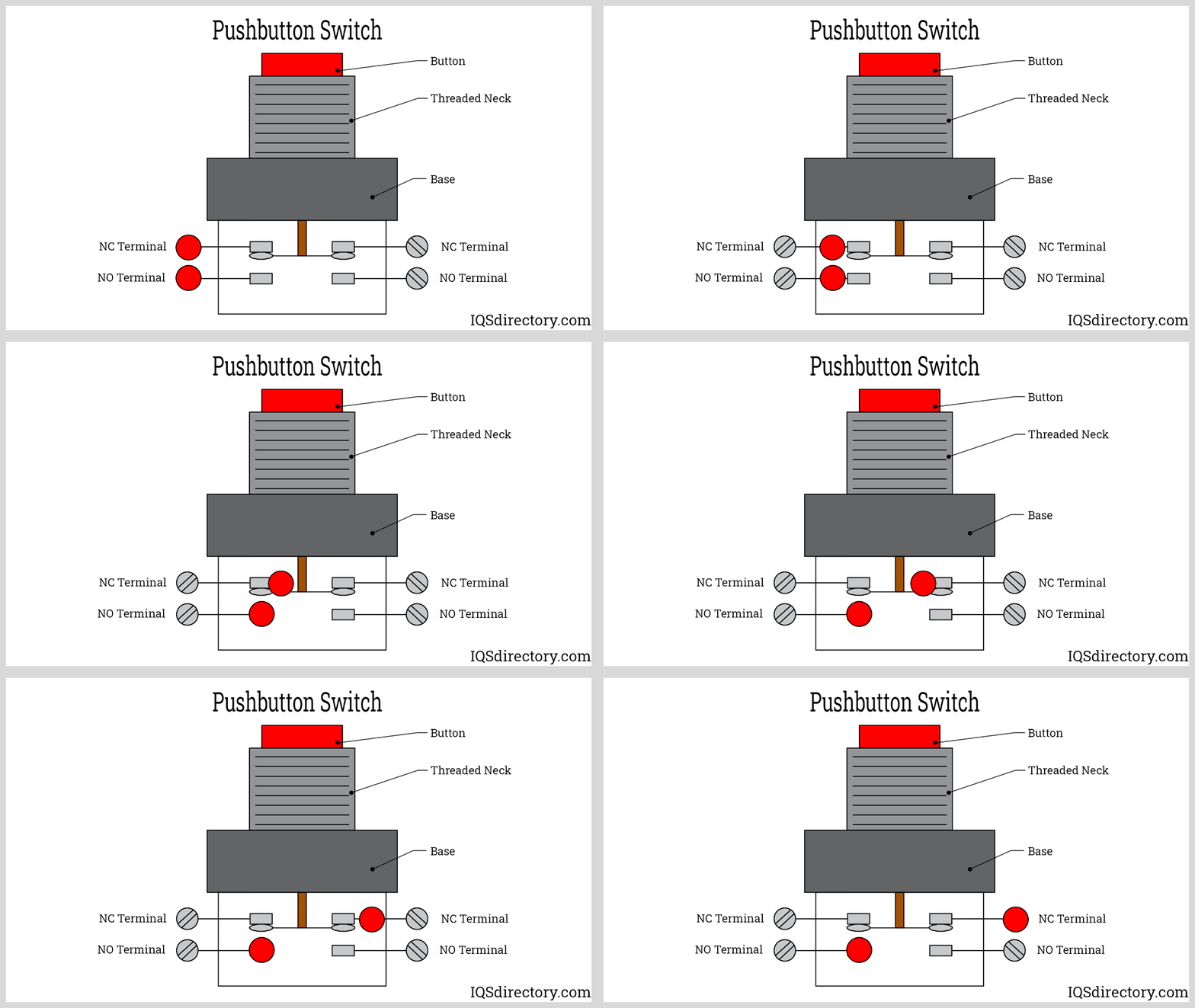
Push button switches come in various designs, such as keys and buttons, and are categorized as either momentary or maintained. The most prevalent kind of momentary switch is the push button. A push button switch that is normally closed, known as a push-to-break switch, will disconnect the circuit upon being pressed. Conversely, a normally open push button switch, or push-to-make switch, will establish the circuit when pressed.
Maintained push button switches differ in that they lock into position until they are pressed again, toggling between locked and released modes. While push buttons usually have two states, there are configurations with more states, although these are rare. Push button switches play a critical role in many applications, from computers and crosswalk signals to industrial machinery, security systems, ATMs, military hardware, slot machines, and fitness equipment, among others.
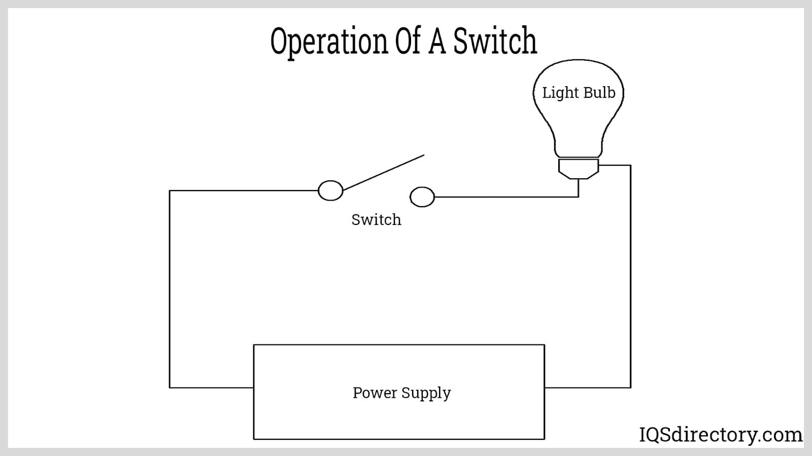
Push button switches function like other types of electrical switches by altering the circuits they are connected to. An open circuit impedes electrical flow, preventing the connected device from operating. Conversely, when a push button switch closes the circuit, it allows electricity to pass through, making the device operational. These switches can be engineered for either a temporary or ongoing closure of the circuit. Some are spring-loaded to return the circuit to its open state when not being pressed.
Interrupting a circuit briefly can facilitate power transfer from one location to another. Push buttons designed to sustain current flow offer distinct on and off positions that toggle with each press. Regardless of the application, push buttons are vital in managing electrical current. Their capability to effectively conduct and interrupt energy as necessary is fundamental. Typically, disconnecting a circuit involves introducing an air gap between contacts that must separate swiftly to achieve the intended outcome. Most electronic switches employ a method of altering the effective resistance within the circuit to change the connection state.
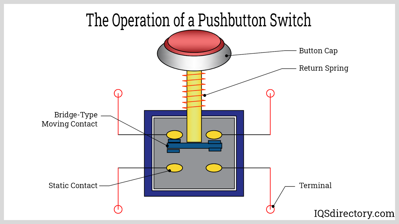
The resistance in switches can be modulated, offering high resistance for an open circuit or low resistance to effectively close the circuit. Typically, push button switches have few moving parts. A vital characteristic is their responsiveness to the actuator, which might be operated either manually or automatically. The actuator is pivotal in enabling or disabling the circuit by changing the state of connection.
Actuations can occur through various triggers such as physical movements, like levers or slides, or by other stimuli like overvoltage or light changes. Frequently, a fuse accompanies the switch to protect the equipment it serves. Considering the diversity of electronic devices, multiple circuitry solutions are required for support.
For instance, a simple light bulb needs just wiring, a switch, and a power source to work, whereas a computer keyboard depends on intricate circuit networks on a circuit board to relay signals to the CPU. Despite this complexity, switches are fundamental for managing circuits in both straightforward and complex applications.
Push button switches are some of the most fundamental electric switches, similar to toggle switches in their basic function of changing circuits. Both types of switches are user-friendly. Operating a push button switch involves pressing it to achieve the intended result. Many push button switches include tactile feedback to help users confirm that the switch has been activated successfully. These switches are widely used in a variety of applications including industrial control panels, consumer electronics, automotive dashboards, and machinery interfaces, thanks to their reliability and versatility.
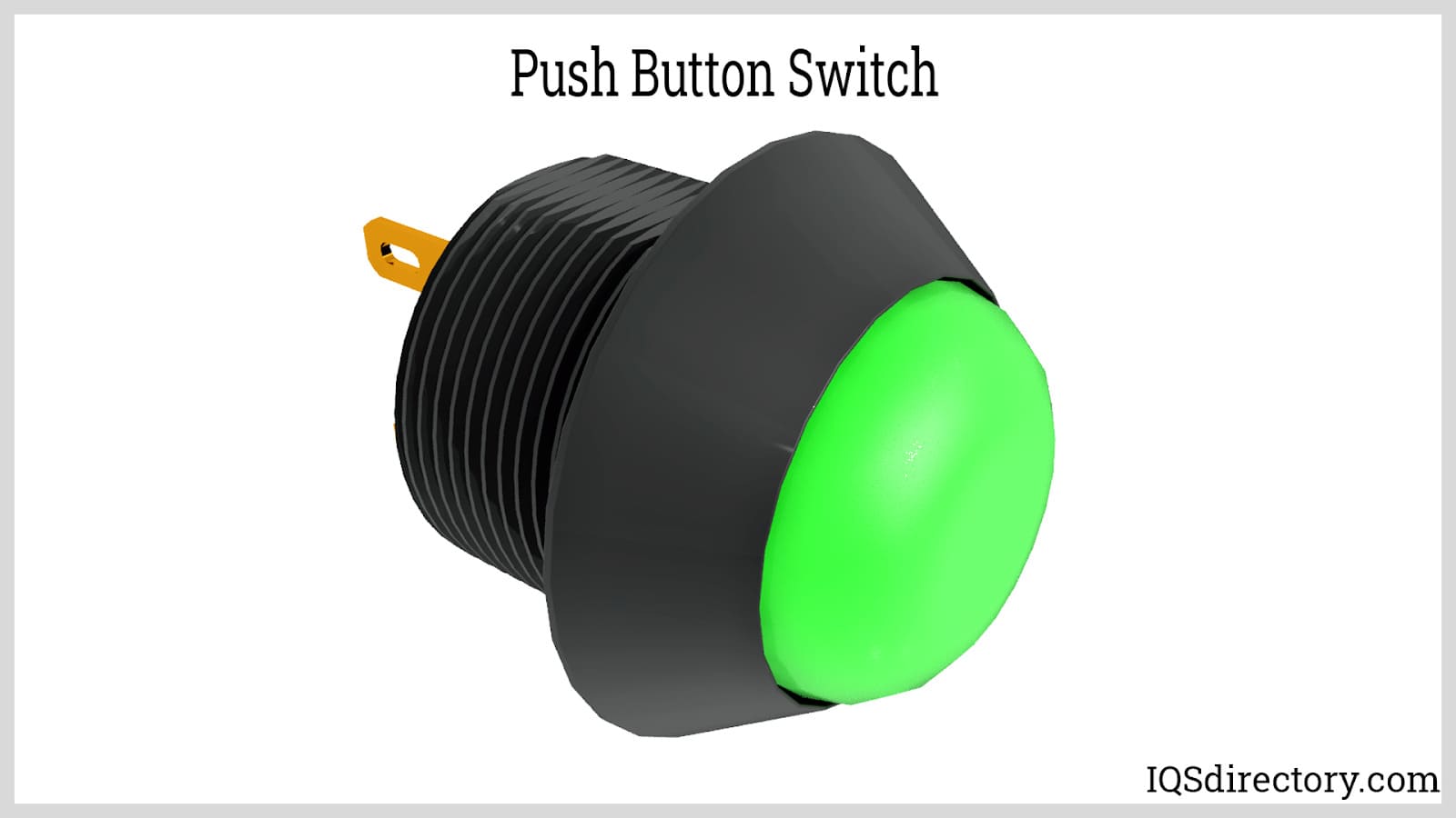
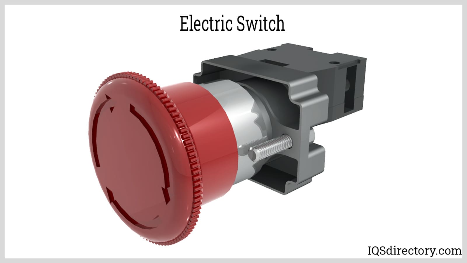
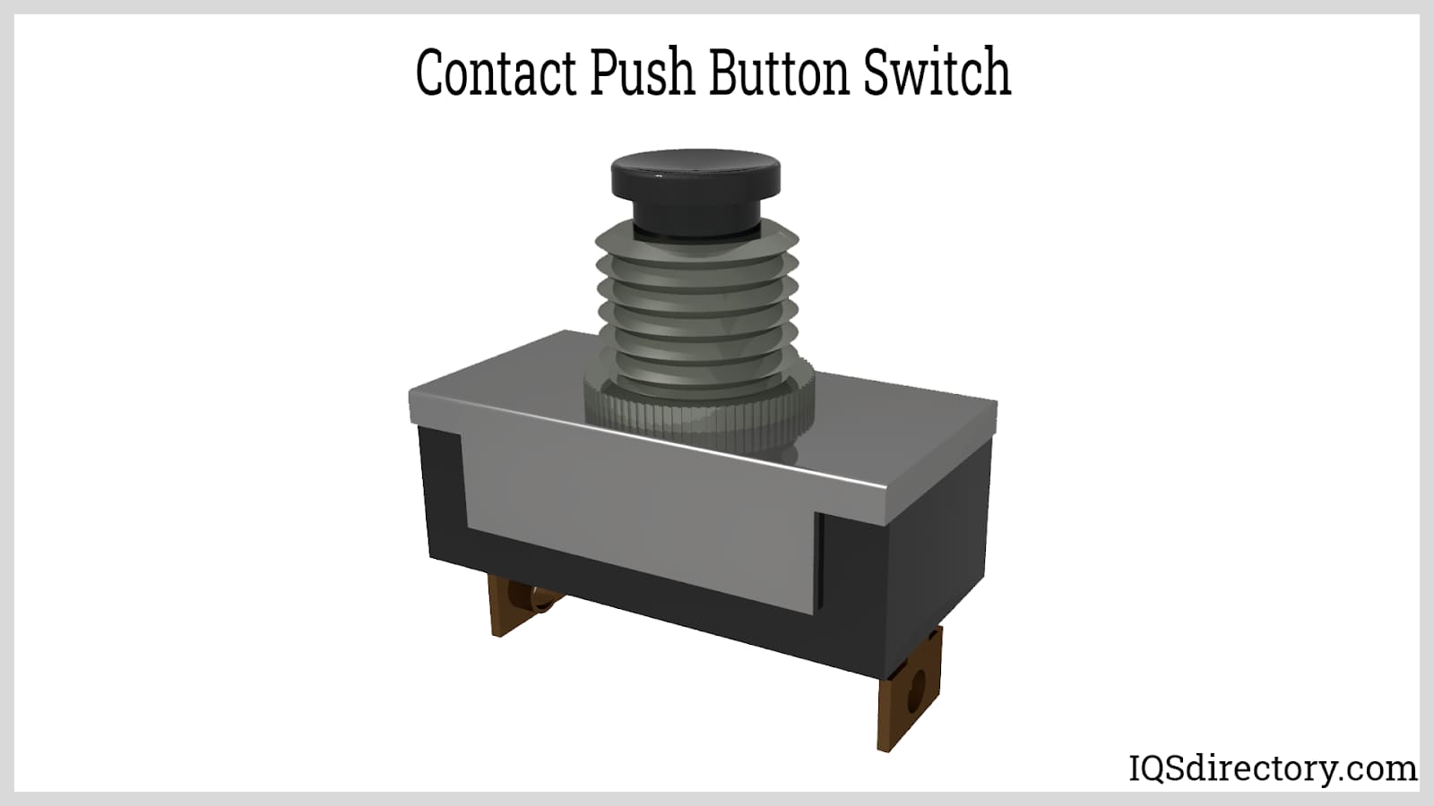
Push button switches come in various configurations: flush, recessed, or elevated. Recessed buttons are set below the surface of the device to prevent accidental activation. Flush switches are level with the surrounding surface, providing a sleek appearance. Elevated buttons protrude above the surface, making them easy to locate and press. Customized push button switches are available with different colors, illumination options (such as LED indicator lights), and symbol engravings to support accessibility and operational clarity for different user environments.
When designing push button switches, engineers and manufacturers often consider the specific requirements of the end application. Some important customization options include:
When selecting a push button switch, end-users and purchasing managers should consider actuation force, life expectancy (number of cycles), mounting style (panel mount, PCB mount), and compliance with standards like RoHS or UL for safety and reliability.
Relays, also known as electromagnetic relays or contactor relays, are electrical devices designed to control a circuit using a separate, often low-power, signal. Essentially, a relay acts as an electrically operated switch. It typically consists of an electromagnetic coil. When an electrical signal energizes the coil, it attracts a metal contact, altering the circuit by either making or breaking a connection. Once the electrical signal is removed, the relay includes a mechanism to return the contact to its default, de-energized position. While the coil is energized, the metal contact remains in its attracted state, making the relay function similarly to a momentary switch.
The latching relay is a type of switch that operates more like a maintained switch. It typically requires signals of opposing polarity to open or close the circuit. Unlike other relays, the absence of power does not affect the controlled switch's state; it remains in its last position until deliberately changed. Latching relays are used when a circuit needs to stay in one state (on or off) for extended periods without continuous power to the coil. They are commonly employed in electrical power supplies to operate circuit breakers and are also found in home automation systems for remote light and load control. Understanding the different types of relays—such as electromagnetic, solid-state, time-delay, and latching relays—helps engineers select the right component for applications that require isolation, circuit protection, or remote switching capabilities.
Previously, telecommunication systems extensively used electromagnetic push button switches for applications such as analog switching, railway signaling, and transceiver selection. The solid-state relay, an alternative to the electromagnetic relay, uses semiconductor components to control separate circuits. A common example of solid-state relay technology is the optocoupler, which connects a light-emitting diode (LED) with a photodiode. Solid-state relays offer faster switching, longer life spans, and increased reliability in electronically controlled systems. The rising trend toward automation, IoT (Internet of Things) integration, and the need for energy-efficient switching solutions continue to drive innovation in relay technology.
Actuator mechanisms in switches are responsible for manually toggling a circuit on and off. In push button switches, these actuators are essential components that control the switch's operation. Essentially, the actuator is responsible for opening and closing the circuit. It is a mechanical part that moves to enable the electrical switch to function properly—without it, the switch cannot operate. Modern actuator designs prioritize both ergonomics and reliability, ensuring a smooth tactile response while meeting safety requirements in industrial, commercial, and residential settings.
There are several types of actuators, each with its own unique operation. For instance, a toggle actuator features a lever that is manually engaged. Depending on its configuration, the switch either opens or closes when the lever is moved. This simple and practical manual operation makes it an effective method for controlling an electrical switch.
Rotary actuators are another type, equipped with a handle that can be turned to open or close the circuit. Users rotate the handle to adjust the switch's state. Until the 1970s, rotary actuators were primarily used in televisions, but today they are more commonly found in radio control devices and measuring instruments. Modern rotary actuators often integrate with digital controls for precise adjustments in laboratory equipment and test benches.
Biased actuators operate using a spring-based mechanism, offering a straightforward way to control an electrical switch. The actuator contains a spring that, when pressed, either opens or closes the circuit. Their simplicity, ease of use, and durability make biased actuators a popular choice among engineers and businesses. Selecting the right actuator helps improve safety, user experience, and functionality, especially in safety-critical or high-traffic environments.
Other specialized actuator mechanisms, such as piezoelectric and capacitive touch actuators, are increasingly used in touch-sensitive switches and electronic keypads for medical devices, instrumentation panels, and consumer interfaces, supporting modern trends in contactless actuation and enhanced device hygiene.
A contactor is an electrical circuit component designed to act as a switch. Its primary function is to establish and interrupt electrical contact. When the contactor is engaged, it closes the circuit, allowing electrical flow. When it is disengaged, it opens the circuit, stopping the flow of electricity. By making and breaking contact, contactors control the flow of electrons, thereby regulating electrical power and signals within a circuit. Contactors are typically constructed from metal or other conductive materials. Industrial contactors are commonly used in motor control and heavy machinery, where reliable and robust switching is essential for energy-efficient and safe operations.

The following materials are commonly used in the production of contactors:
Copper and Copper Alloys: Copper is an excellent conductor of both electricity and heat, second only to silver in conductivity. Brass, a popular copper alloy, is frequently used in contactor manufacturing.
Silver and Silver Alloys: Silver offers superior electrical conductivity, potentially the highest among all metals. Additionally, silver and its alloys are resistant to oxidation, making them valuable for contactor applications.
Gold and Gold Alloys: Gold is an effective conductor, following copper and silver in conductivity. It also exhibits excellent corrosion resistance. However, due to its scarcity and high cost, gold is rarely used in contactors.
Platinum Group Metals: Platinum is one of the most expensive materials used in circuitry. Given its high specific weight, the value of platinum for contactors is often questioned, especially since volume considerations typically outweigh weight.
Carbon as a Conductor: While carbon is a nonmetal, certain forms of it can conduct electricity. Although it is less effective compared to metals, carbon is used in specific industrial applications, such as in certain batteries and renewable energy systems, as well as for experimental and recreational purposes.
Other Metals: Various other metals also conduct electricity and are used in different applications where resistance is less critical. Examples include:
Understanding which materials are used for contactors and connection points in push button switches is essential for ensuring maximum electrical performance, safety, and product longevity. When evaluating or purchasing push button switches, customers should consider both the application environment (such as exposure to moisture, chemicals, or vibration) and the electrical load requirements. Leading electrical component suppliers provide detailed datasheets specifying material types, conductive properties, contact resistance, and rated voltage/current, assisting buyers in making informed decisions for their projects or processes.
Push button switches are essential components in electric and electronic circuits, known for their wide application in industrial automation, consumer electronics, control panels, and machinery interfaces. They are typically categorized by their default circuit state as either normally open (NO) or normally closed (NC) push button switches. A normally open switch breaks the circuit when not activated and completes the circuit, turning the device "ON"—or energizing it—when pressed. Conversely, a normally closed switch maintains a closed circuit, keeping the device powered, and only interrupts (turns "OFF") the power when pressed.
Additionally, push button switches are further defined by their switching circuit configurations, such as single pole, single throw (SPST), single pole, double throw (SPDT), double pole, single throw (DPST), and double pole, double throw (DPDT). Each of these circuit types determines how the switch routes electrical current, allowing for flexibility in switching single or multiple circuits. Understanding these distinctions helps users select the ideal push button switch for specific applications, whether for control panels, safety circuits, machine interfaces, or custom electrical projects.
A normally open (NO) push button switch is an electrical switch designed to have separated contacts in its default state. This means no electric current flows when the switch is unpressed, keeping the device or load powered off. Upon pressing the NO push button, the contacts close, completing the circuit and activating the connected device. This property makes them suited for start buttons, machine activation, and signal controls across a variety of settings—including automation systems, consumer gadgets, and security devices.
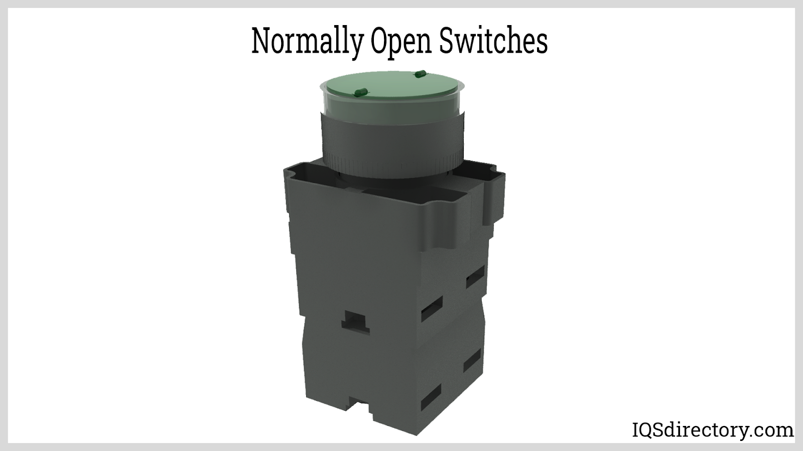
Momentary push button switches are a subset of NO switches that only stay closed while pressure is applied, commonly used for applications like doorbells, keyboard keys, and machine start controls. Conversely, latching push button switches stay in their new state once pressed, maintaining the circuit until pressed again. These latching switches are widely implemented in on/off switching for lights and appliances.
Light Switch – Most residential and commercial light switches employ a normally open latching mechanism. Pressing the switch closes the circuit and keeps the light on until switched again, ensuring reliable room lighting or equipment control.
Medical Bed Controls – Medical bed controls often use normally open momentary switches in the form of footswitches or hand controllers. Continuous pressure actuates the switch, enabling precise adjustment of bed position; releasing pressure opens the circuit, halting movement and enhancing patient safety.
Medical and Industrial Equipment – Many medical devices and industrial machinery rely on normally open momentary push buttons for hands-free operation or emergency stops. For example, footswitches or hand-activated momentary switches help operators maintain operational control without diverting focus from their tasks. Examples include:
Additional use cases for NO push button switches include alarm system triggers, remote-control interfaces, and automation panels—where momentary contact provides precise and responsive control.
A normally closed (NC) push button switch maintains closed contacts in its resting state, allowing electrical current to flow and power devices until the switch is actuated. Pressing the NC button forces the contacts open, breaking the circuit and instantly cutting power to the connected load. NC push buttons are critical for safety interlock systems, emergency stop (E-stop) switches, and fail-safe automation configurations—ensuring that machinery or equipment is powered down in the event of abnormal conditions or operator intervention.
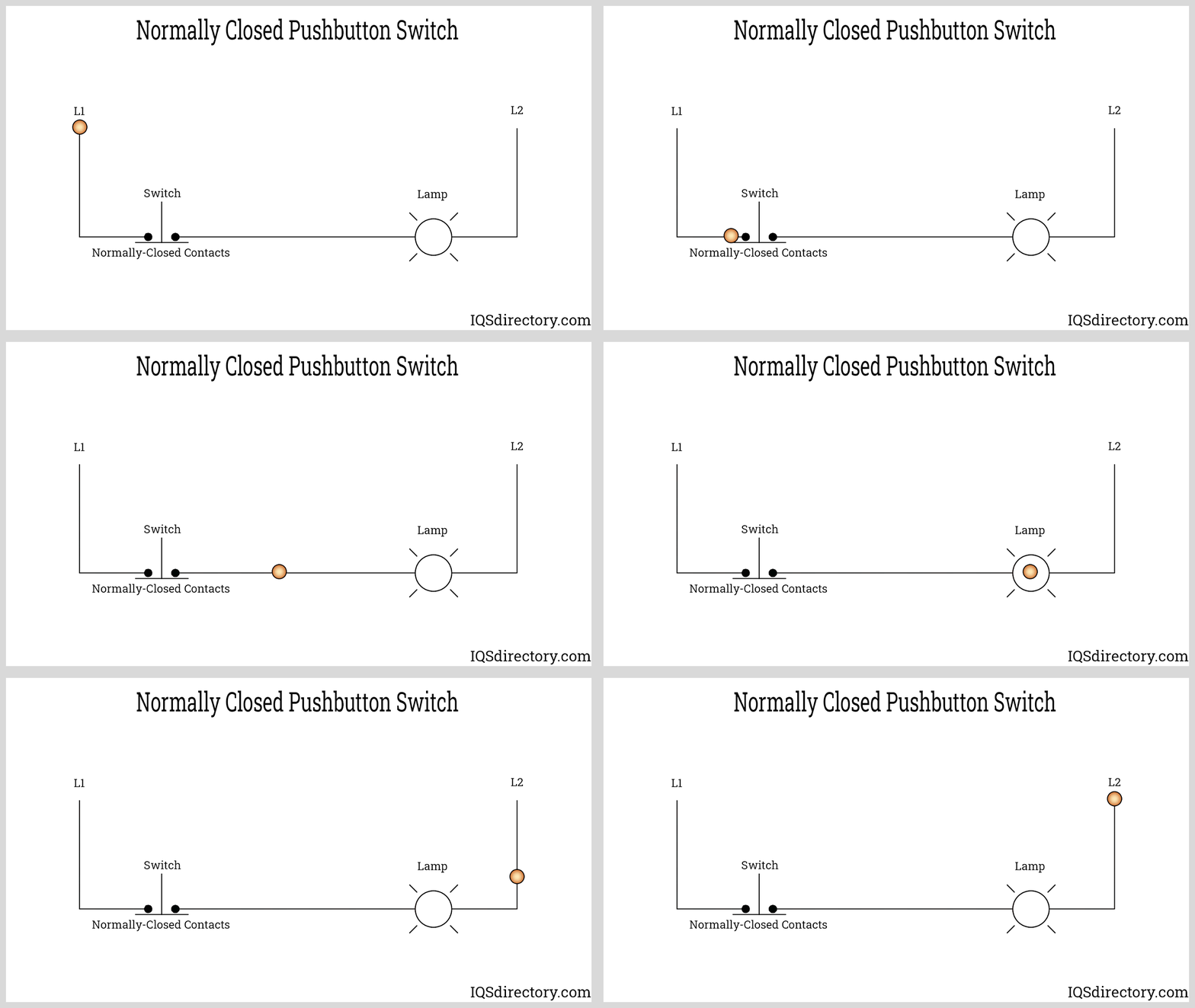
A primary advantage of the normally closed configuration is its "fail-safe" capability, making it the default choice for stop, shutdown, and safety circuits. When the switch is not pressed, current flows uninterrupted; pressing the button immediately disconnects the power, stopping motion, disabling hazardous equipment, or isolating circuits—crucial for electrical and industrial safety protocols.
The single pole, single throw (SPST) push button switch is the simplest type of switch, featuring one input (pole) and one output (throw). Its sole function is to provide straightforward ON/OFF control—ideal for basic lighting circuits, power supplies, and auxiliary device activation. SPST switches are frequently found in high-voltage systems (such as 25kV railway DC applications) and household lamp controls.

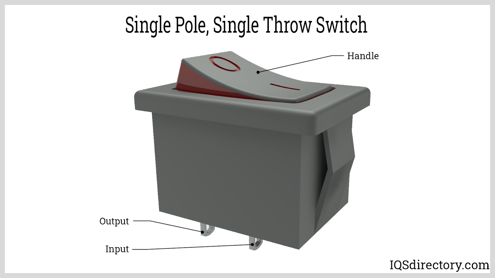
SPST push button switches provide two main terminal connections: the common (C) and the normally open (NO). Pressing the button closes the contacts, allowing current to flow from the common to the NO terminal, thus energizing the load. They are popular for simple manual switching, such as toggling room lights, activating control panels, or powering external tools and devices with minimal wiring.
Some benefits of the SPST switch include:
The drawbacks of the SPST switch include:
Users seeking solutions for basic ON/OFF switching in both industrial and home applications will benefit from understanding when an SPST push button offers optimal performance and cost-effectiveness.
The single pole, double throw (SPDT) push button switch offers the ability to alternate an input signal between two different outputs, making it highly versatile for complex controls and signal selection. SPDT switches are commonly used in relay circuits, selector switches, changeover controls, and multi-mode lighting or device applications. They can be operated manually or automatically (via an electromagnetic relay), allowing the routing of current to different circuit branches as required.
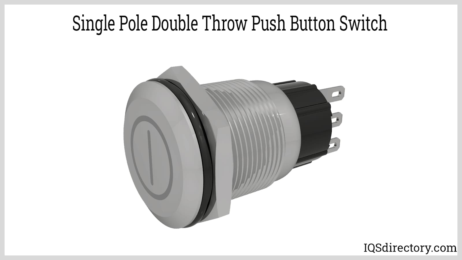
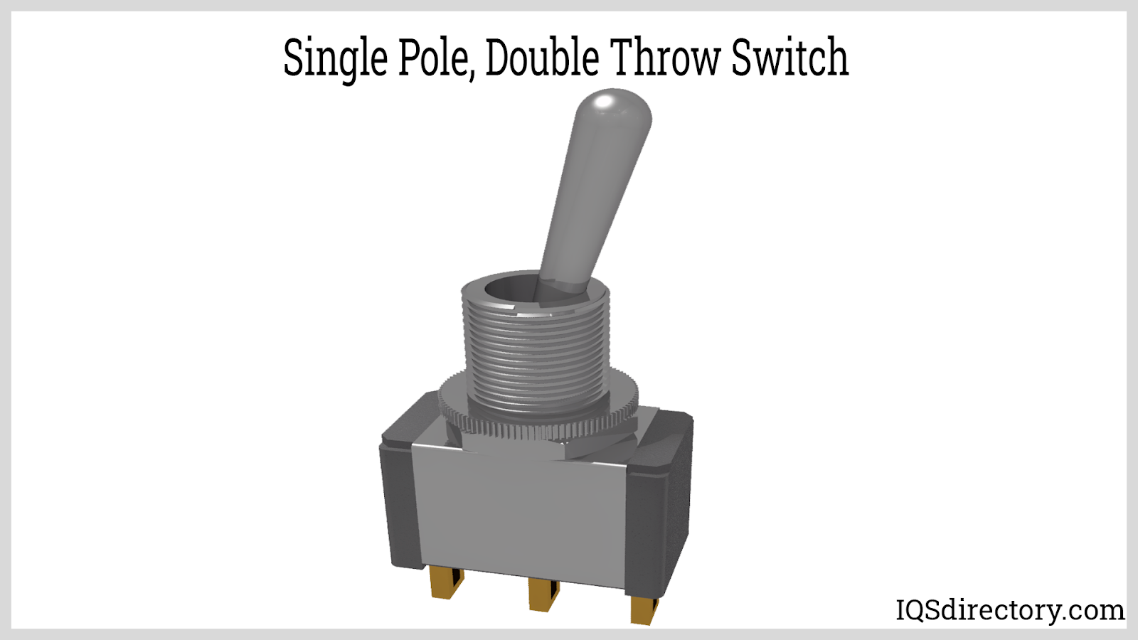
In industrial automation and control, SPDT push buttons are integral for PLC signal routing, machine function toggling, and alternate device selection. Depending on application requirements, SPDT switches can be divided into:
BBM or open transition switches momentarily break the circuit before transferring the connection, which is vital in transfer switches and industrial applications where electrical isolation is required during changeover.
Devices with multiplexing requirements, or systems where simultaneous electrical connection of both outputs would cause damage or interference, depend on BBM functionality for safety and reliability.
MBB or closed transition switches briefly connect both outputs during the switching process, guaranteeing consistent current flow for sensitive circuitry like audio switching, analog multiplexers, and feedback circuits.
The MBB structure is ideal for applications requiring continuity without momentary interruption, such as in feedback control systems, stereo switching, or redundant power supplies.
When selecting an SPDT switch, evaluating whether your circuit demands BBM or MBB functionality helps ensure optimal performance, safety, and longevity in your electrical and electronic systems.
The double pole, single throw (DPST) push button switch contains two separate inputs (poles) that connect to their respective outputs through a single switching action. Both circuits are simultaneously controlled by one actuator—either engaging or disengaging both together. DPST push buttons are valuable in dual-supply equipment, mains isolation switches, and industrial machines requiring simultaneous disconnection of phase and neutral lines for safety and compliance.
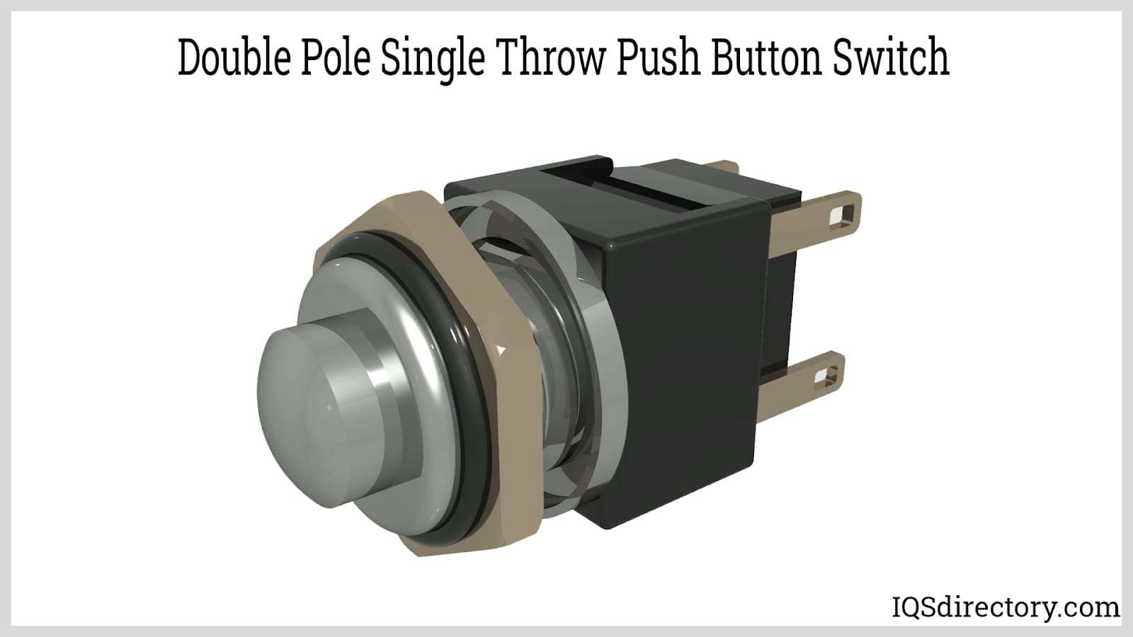
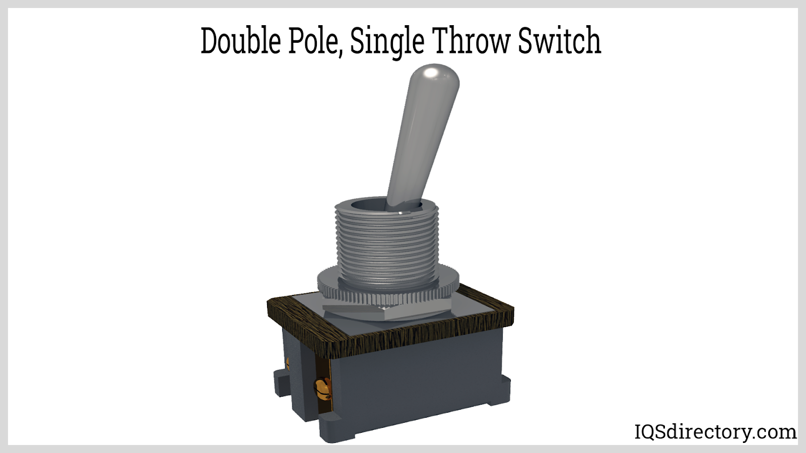
A DPST push button combines two independent SPST switches, enabling users to simultaneously control or isolate two electrical circuits with one action. This is a common requirement in power distribution, HVAC units, and equipment utilizing multiple power sources or high-load circuits that demand synchronized activation or shutdown for safety and efficiency.
The DPST switch offers the following advantages:
Some potential drawbacks of the DPST switch are:
This makes the DPST push button vital for electrical engineers and installers seeking compliance with electrical safety standards and wanting dependable control in multi-circuit machinery.
The double pole, double throw (DPDT) push button switch expands the SPDT design by allowing two independent circuits to each be connected to one of two outputs, essentially offering two SPDT switches controlled by a single actuator. Equipped with six terminals—two inputs and four outputs—DPDT switches facilitate versatile circuit routing, mode selection, and polarity reversal, which is critical in applications such as motor control, power relays, and audio routing.
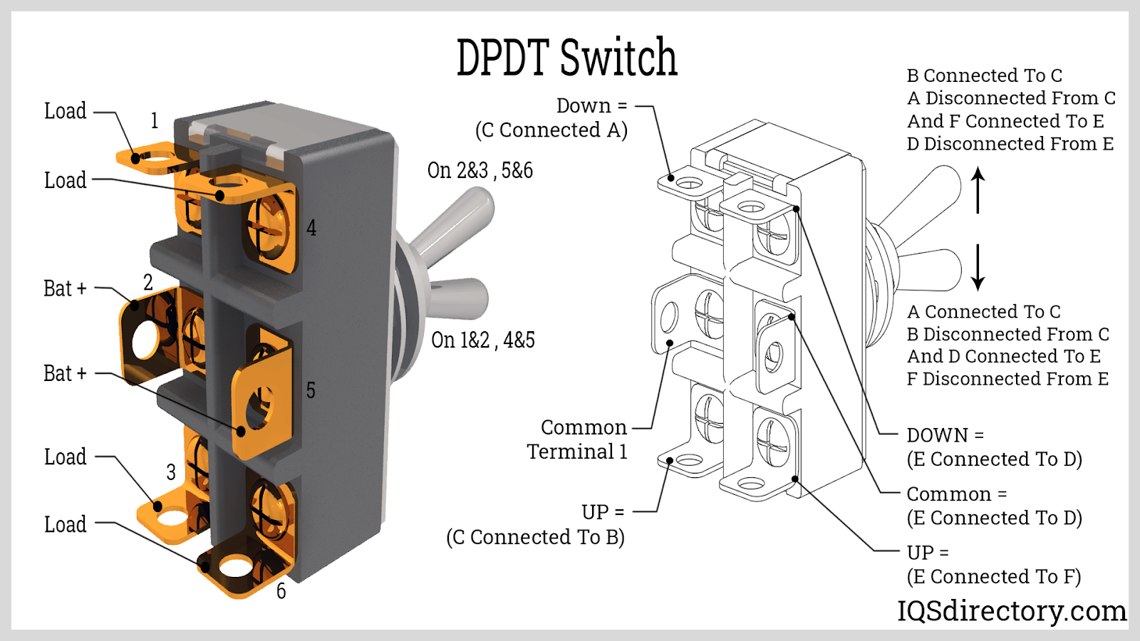
Key uses of DPDT push button switches include controlling forward/reverse operation in DC motors, switching two devices between different power sources, or effecting situation-dependent failover in complex AC/DC systems. The configuration supports both momentary and maintained actions, providing flexibility for machine designers, automation engineers, and electronic hobbyists alike.
Some major advantages of DPDT switches include:
Some drawbacks of the DPDT switch include:
To optimize usage, always assess application requirements for circuit complexity, needed isolation, and safety compliance. DPDT push buttons are the go-to choice for engineers and buyers seeking robust, multi-functional, and reliable switching solutions in high-performance environments.
For further details on selection, installation, or purchasing options for push button switches—including data sheets, technical support, and compatibility advice—consult an industry-recognized push button switch supplier or a trusted electrical components distributor to ensure correct fit and long-term performance in your application.
Momentary push button switches only remain active while pressed, returning to their original state when released. Maintained switches lock in their new position after being pressed and require another press to return to the previous state.
A normally open (NO) switch completes the circuit only when pressed, turning a device on. A normally closed (NC) switch breaks the circuit when pressed, turning a device off. NO is commonly used for start functions, while NC is used for safety and emergency stops.
Push button switches can be customized in colors, illumination (LED indicators), engraving, environmental protection (waterproof, dustproof), actuation force, life expectancy, mounting style, and terminal types for application-specific needs.
Contacts are typically made from copper, copper alloys (brass), silver, gold, platinum, and sometimes carbon. Metals like silver and copper are chosen for superior conductivity and corrosion resistance, ensuring reliable performance and long life.
SPST switches control a single circuit with ON/OFF action. SPDT switches toggle a single input between two outputs. DPST switches control two circuits simultaneously. DPDT switches route two separate circuits to two outputs, enabling versatile control and functions like polarity reversal.
In industrial environments, push button switches are used for machinery control, emergency stops, safety interlocks, panel interfaces, and actuation in automation systems, thanks to their reliability and ability to handle high-load and safety-critical operations.
This chapter will explore the applications, advantages, and limitations of push button switches.
Push button switches are used in a variety of commercial and domestic applications. Some of the most common applications include:
Calculators: Push button switches in calculators are tactile switches that complete an electric circuit when pressed and break the circuit when released. This requires physical interaction to turn the button on or off. Calculators, which often feature numerous small push button switches, use these buttons to input data. The logic circuit within the calculator regulates power supply connections based on the state of these push buttons on the keypad.
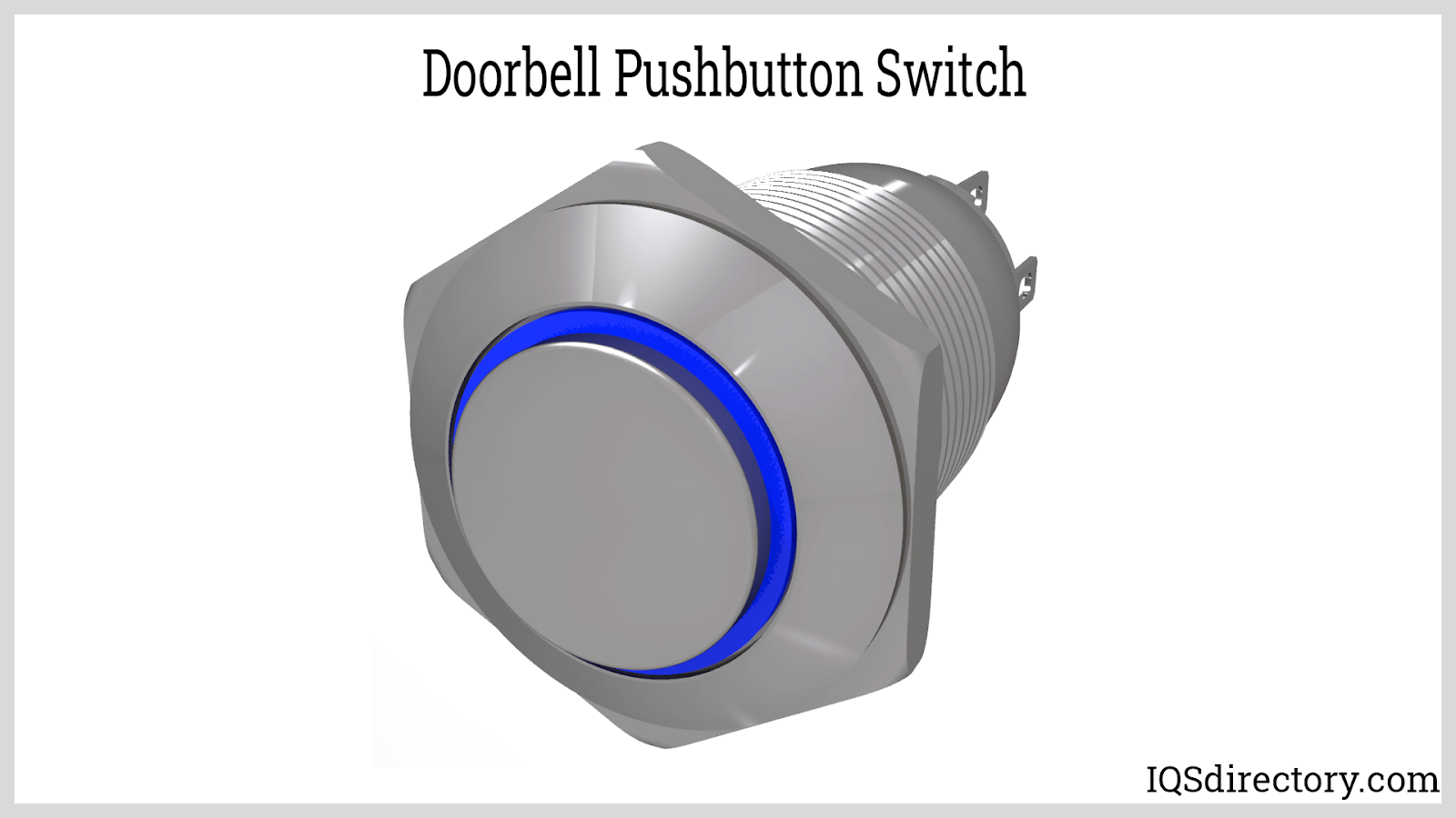
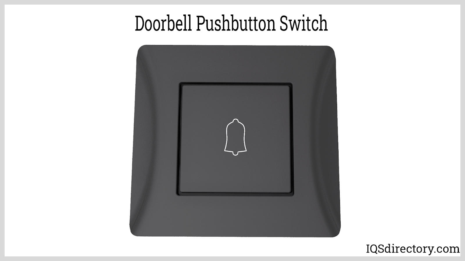
Doorbells: Doorbells are commonly used worldwide and are designed for intermittent use rather than continuous operation. Historically, doorbells used electromagnets to activate a hammer that struck a bell to produce sound or melody, with the sound continuing until the circuit was de-energized. Modern doorbells incorporate push button switches that can become annoying if pressed continuously, as they trigger the doorbell's sound mechanism.
Push Button Telephones: Telephones feature numerous buttons or push switches for dialing numbers. Modern push button telephones often include electronic controls that offer additional functionalities, such as last number redial and storage of frequently dialed numbers, enhancing their usability. Some models also provide advanced features like data coding, information retrieval, and PIN entry.
Advanced Machine Controls: Push button switches are designed to facilitate complex control systems, making them user-friendly for operators. These systems can be equipped with various software programs and color-coded buttons to indicate their status. For instance, in many systems, a red button typically denotes the power function, while a yellow button may indicate a pause. These color codes are standardized internationally for a broad range of industrial applications.
Push button switches have a broad range of applications beyond those mentioned. They are commonly found in casino games, high-security systems, fitness equipment, and many other diverse settings.
Push button switches have transformed switch design, enhancing their efficiency. Some of the key benefits of using push button switches include:
Additional benefits of push button switches include:
Push button switches are designed with special sealing techniques, making them waterproof, oil-proof, resistant to pollutants, anti-static, and capable of withstanding contamination and interference.
They are also cost-effective to manufacture; some membrane switches can be produced for just a few cents each. This low cost provides significant commercial advantages for versatile electronic components.
Another advantage is their compact and lightweight nature. Illuminated push button switches are particularly easy to transport and install due to their minimal weight.
Moreover, push button switches offer excellent electrical conductivity. They can use copper foil, silver paste, or carbon paste to print the circuit, and their unique membrane design can handle higher voltages and allows the conducting layer to be folded without performance degradation.
Push button switches also provide a long service life and an appealing appearance. While many electronic switches have a good look and durability, these features are especially notable in push button switches.
However, there are several drawbacks to using push button switches, including the following:
Push button switches are electrical actuators that, when pressed, either close or open an electrical circuit. The actuator of a push button switch is a button or key, which can be permanent or temporary. Push button switches are normally open (NO) or closed (NC). When triggered, they complete a circuit. When closed, they break a circuit. They can be characterized by their functionality and the switching circuit they use, which can be:
Push button switches are used in a wide range of applications, including computers, crosswalks, telephones, industrial machinery, security systems, ATMs, military equipment, casino gambling slot machines, fitness equipment, and gadgets.

An electric switch is a device – usually electromechanical – that is used to open and close an electric circuit. This disables and enables the flow of electric current, respectively...
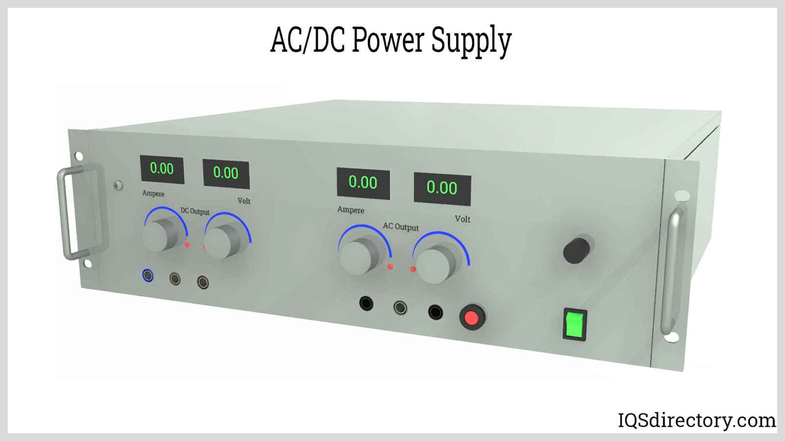
Power supplies are electrical circuits and devices that are designed to convert mains power or electricity from any electric source to specific values of voltage and current for the target device...
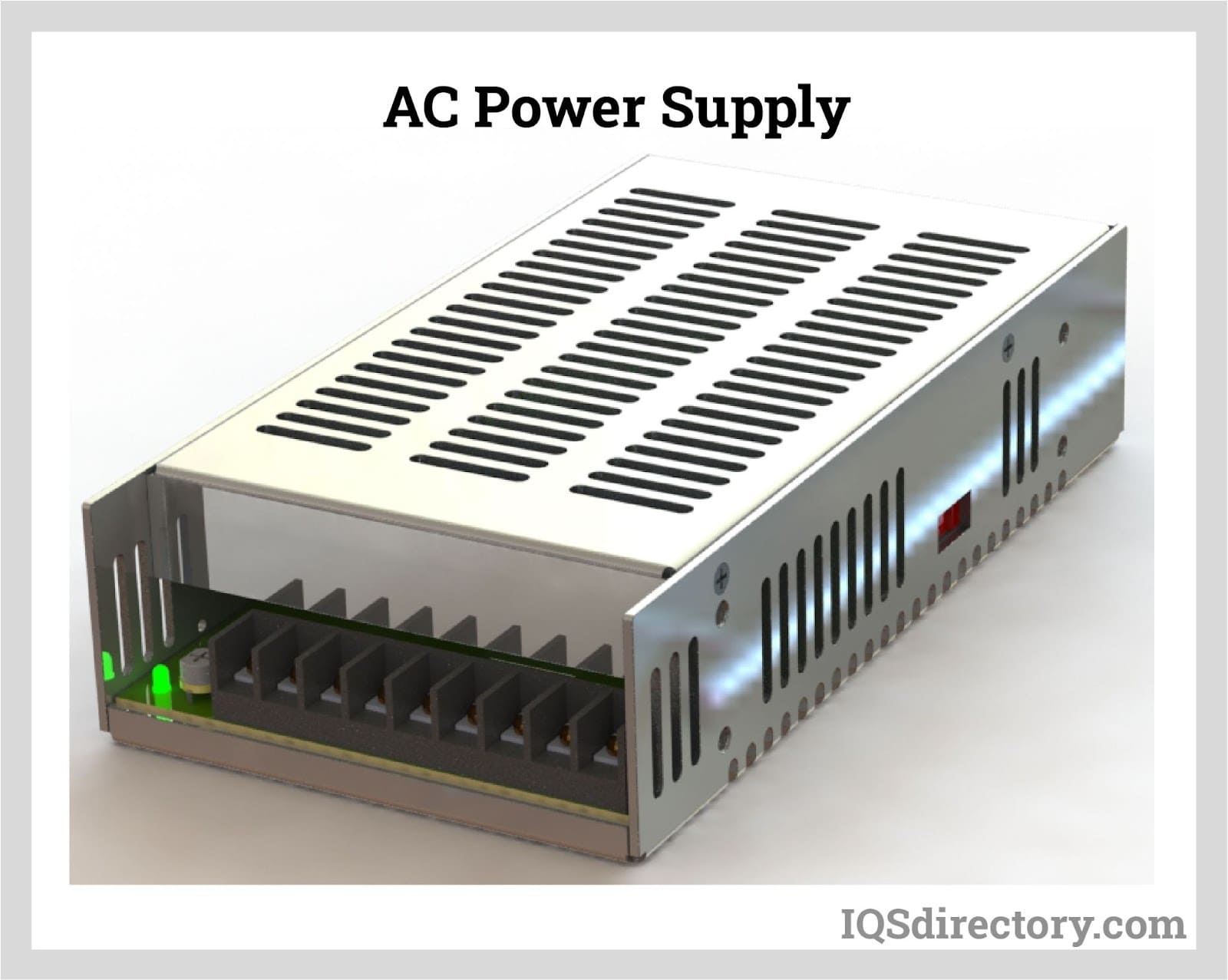
An AC power supply is a type of power supply used to supply alternating current (AC) power to a load. The power input may be in an AC or DC form. The power supplied from wall outlets (mains supply) and...
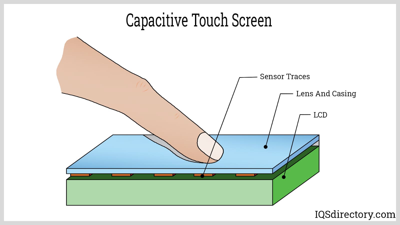
A device's display screen that uses finger pressure for interaction is called a capacitive touch screen. Handheld capacitive touch screen devices generally link to networks or computers using an architecture that can...
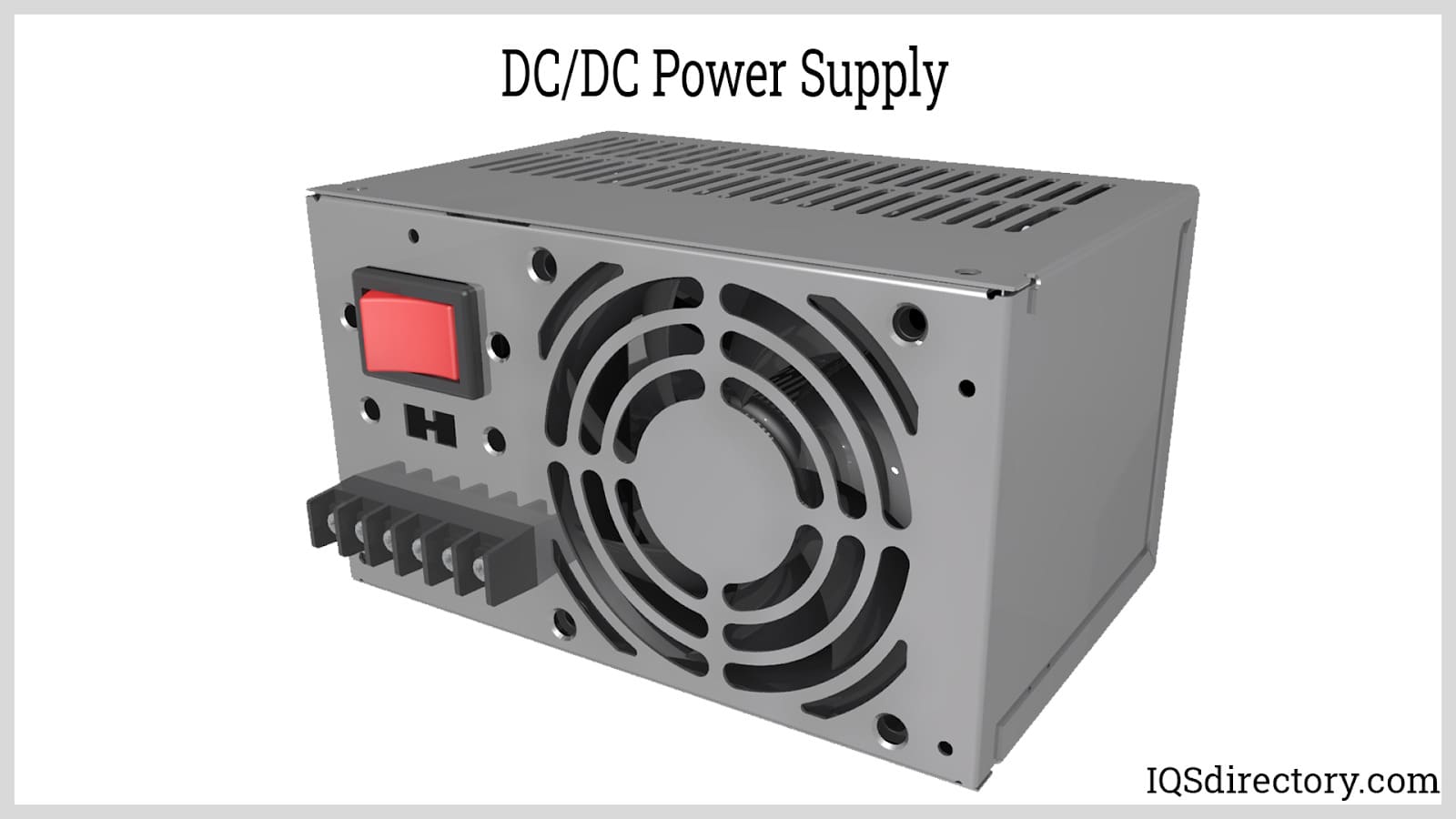
A DC DC power supply (also known as DC DC Converter) is a kind of DC power supply that uses DC voltage as input instead of AC/DC power supplies that rely on AC mains supply voltage as an input...
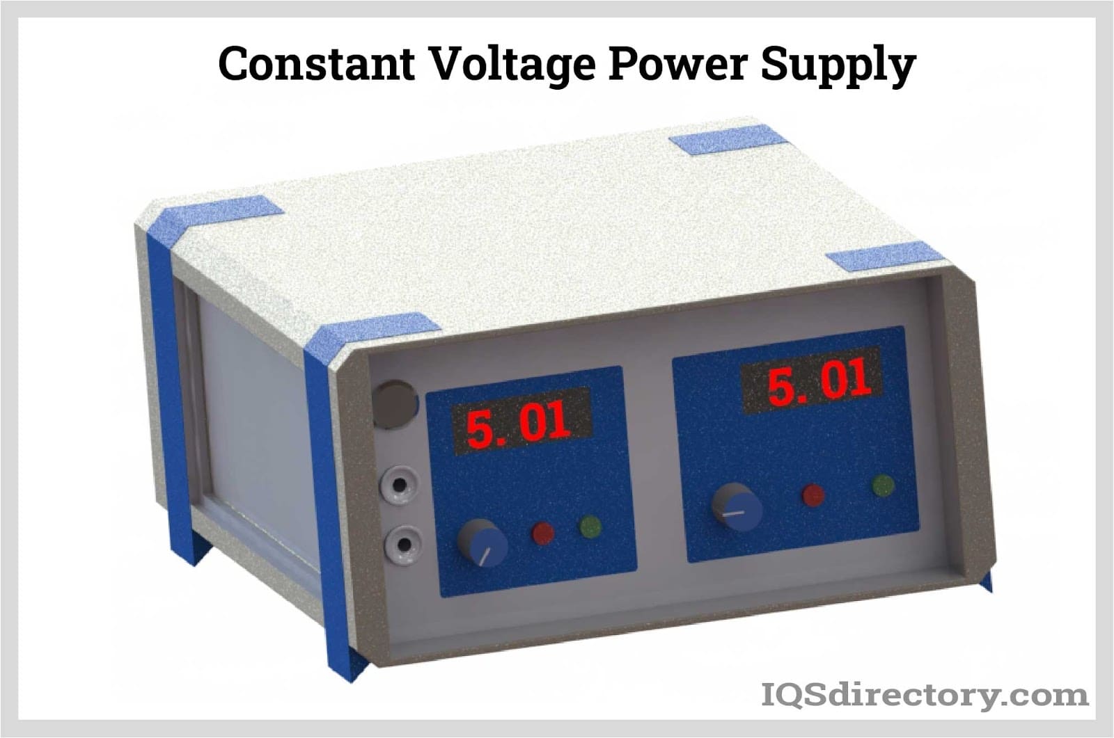
A DC power supply is a type of power supply that gives direct current (DC) voltage to power a device. Because DC power supply is commonly used on an engineer‘s or technician‘s bench for a ton of power tests...
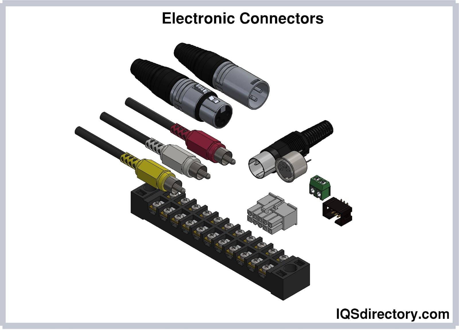
Electronic connectors are devices that join electronic circuits. They are used in assembling, installing, and supplying power to electrical devices. Connectors are an important component of every electronic equipment used in...
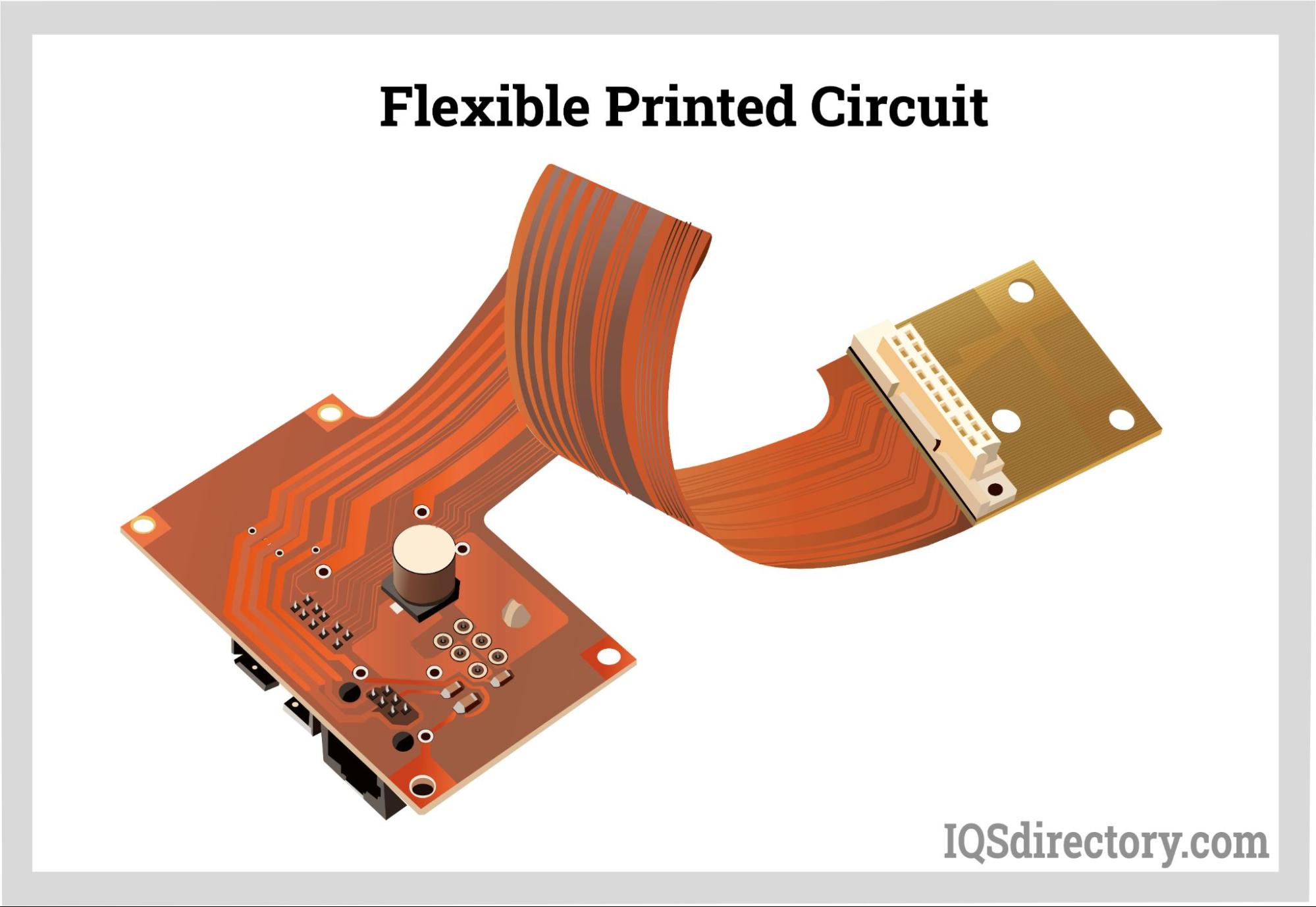
Simply put, a flexible printed circuit (abbreviated FPC) has conductive traces on a thin, flexible substrate. "Flexible printed circuits." are circuit boards that can twist or bend. This claim makes it clear that they can be distinguished by...
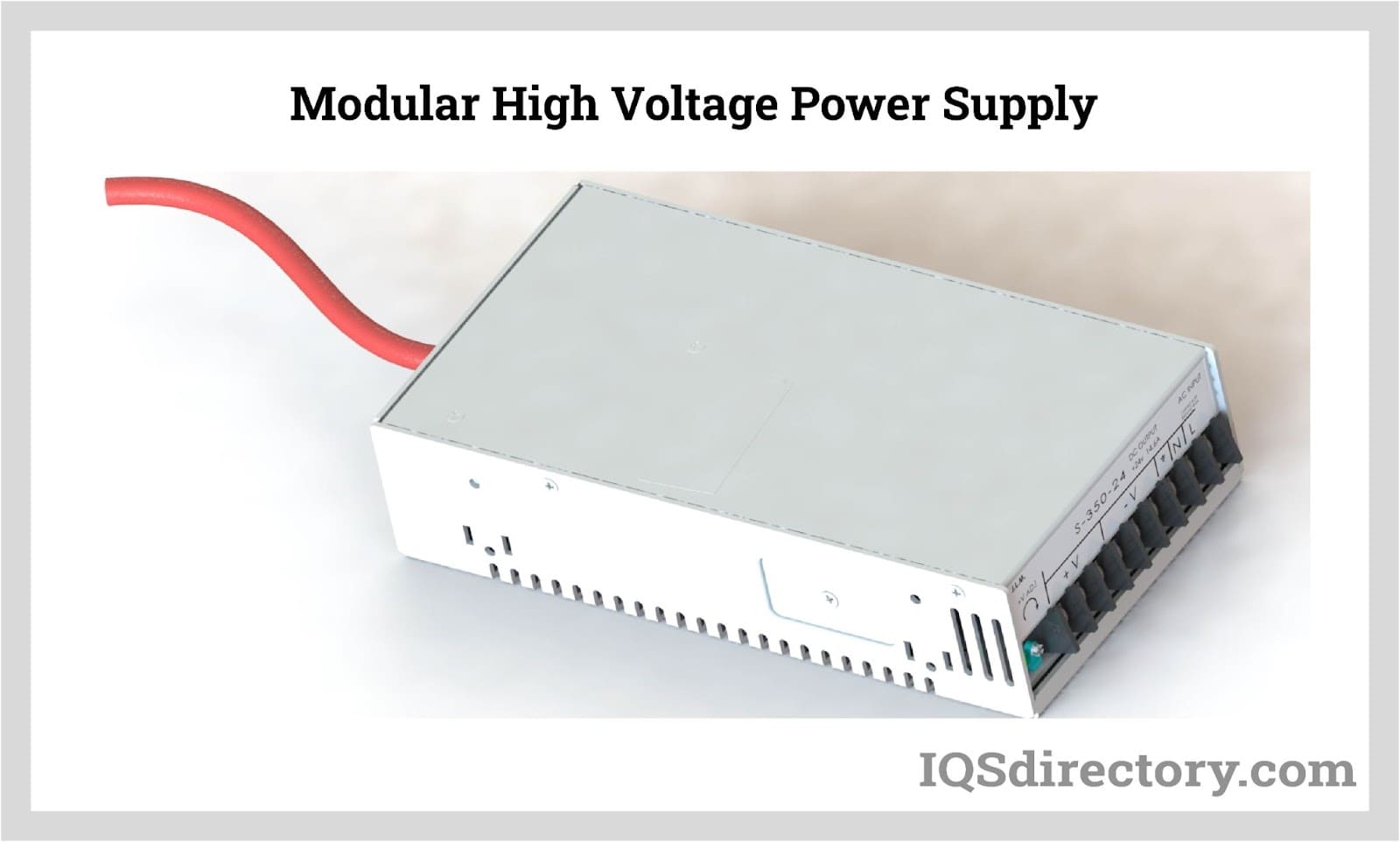
By definition a power supply is a device that is designed to supply electric power to an electrical load. An electrical load refers to an electrical device that uses up electric power. Such a device can be anything from...
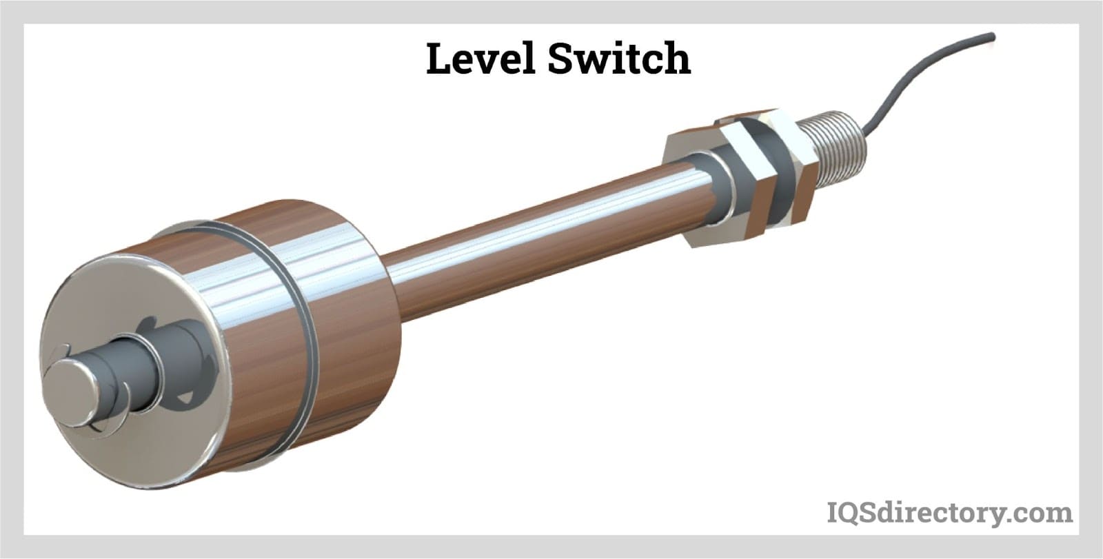
A level switch is an electrical or mechanical method for measuring the level of a liquid, powder, or granule material. It is designed to activate an alarm if the material level in a container passes a predetermined height or depth...
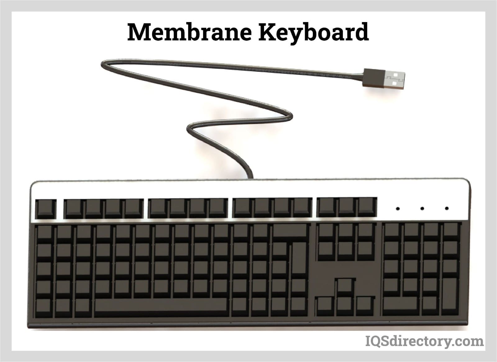
A membrane keyboard is a type of keyboard technology found in many electronic gadgets and appliances. A keyboard, as we all know, is essential hardware that...
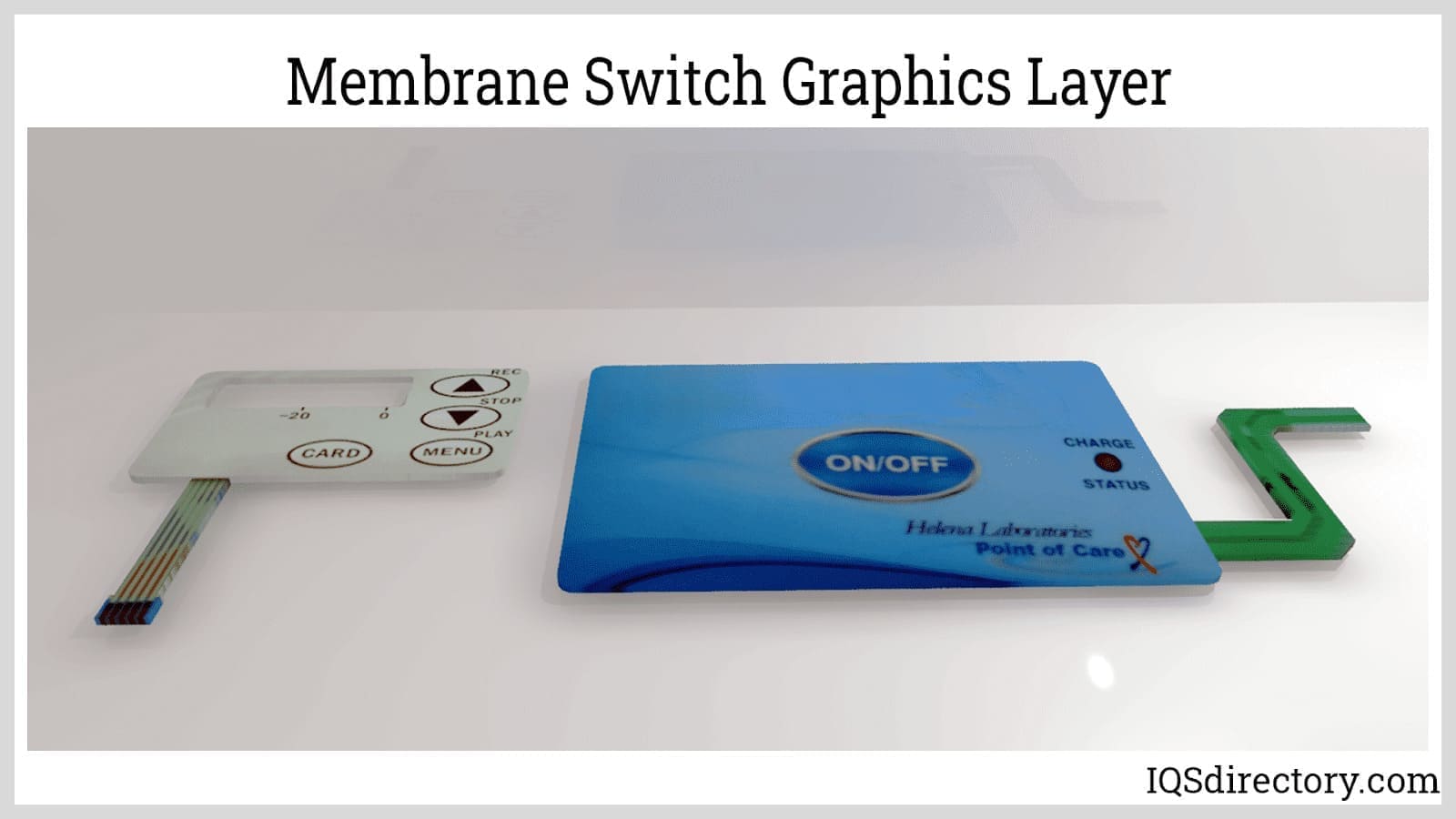
Membrane switches are a type of human-machine interface characterized by being constructed from several layers of plastic films or other flexible materials...
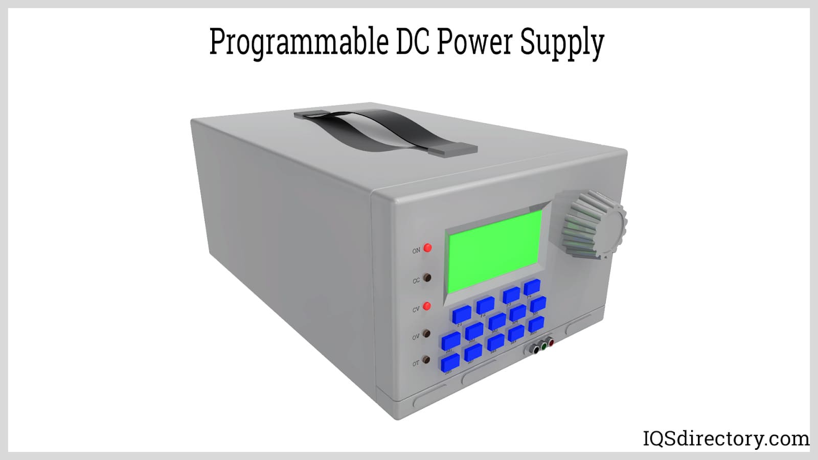
A programmable power supply is a method for controlling output voltage using an analog or digitally controlled signal using a keypad or rotary switch from the front panel of the power supply...