Automatic Screwdrivers
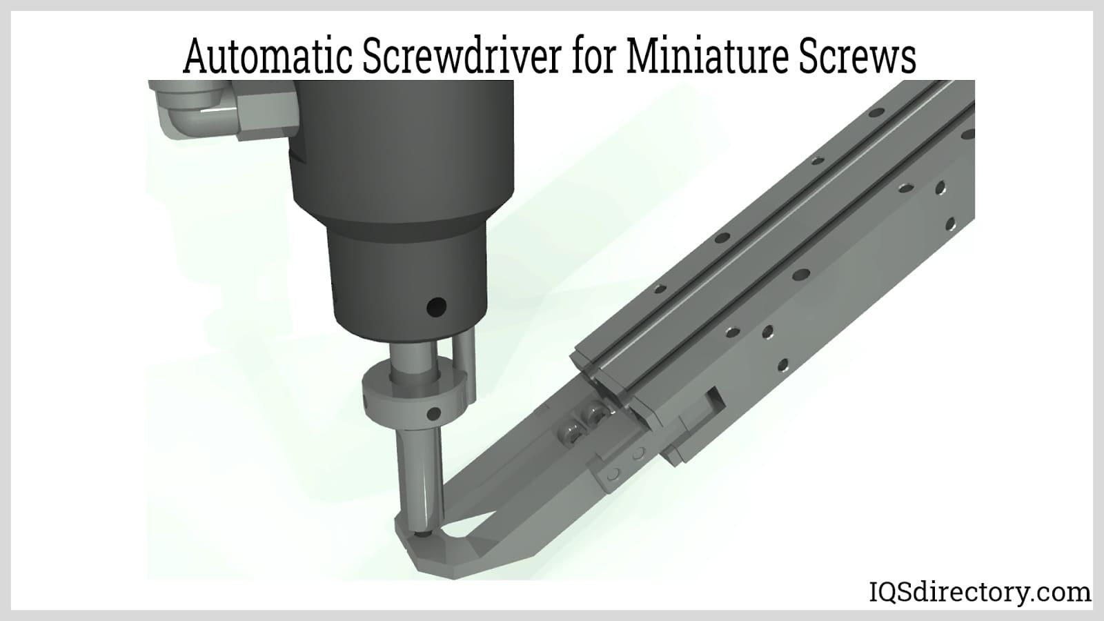
An automatic screwdriver is a piece of equipment that automatically inserts screws into a product during assembly and production. Since every production operation is unique and requires a...
Please fill out the following form to submit a Request for Quote to any of the following companies listed on
This article offers industry insights about automation systems with a primary focus on arms and actuators. Read further to learn more about:
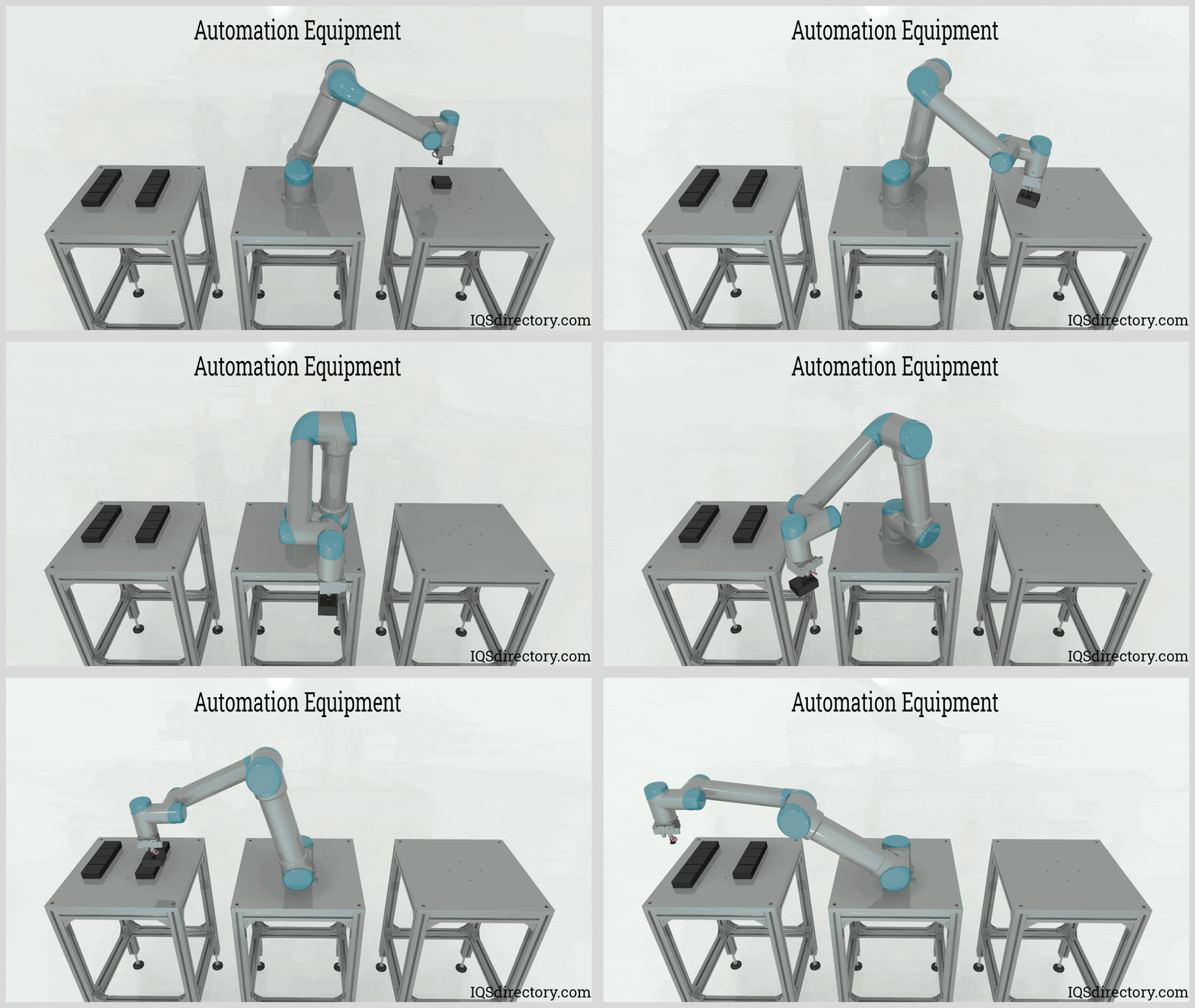
An automation system integrates sensors, control elements, and actuators to execute tasks with minimal or no human intervention. This cutting-edge technology is a part of the Mechatronics field, an interdisciplinary branch of engineering integrating mechanical, electrical, and electronic systems.
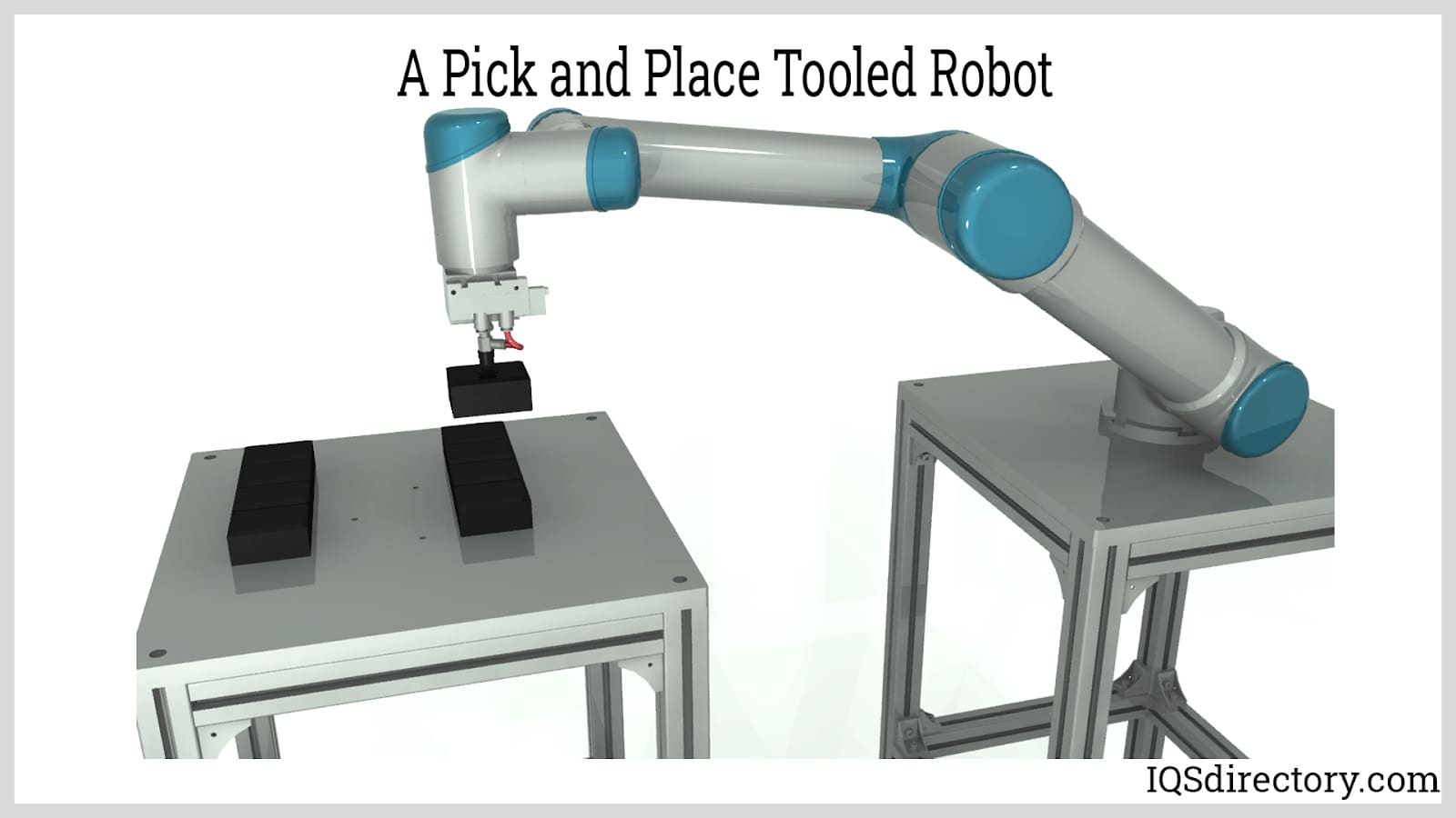
Generally, automation systems are derived from traditional manual operations such as drilling, cutting, and welding. These systems frequently employ robotic arms to manipulate the tools necessary for executing these tasks. In applications focused on process control, automation systems observe and modify process parameters by operating equipment like heaters, motors, pumps, and compressors, or by managing process routes with valves. Automation systems are available in a variety of configurations tailored for distinct tasks. Some prevalent applications include:
The primary goal of an automation system is to minimize human intervention in industrial, manufacturing, and production processes. Human operators are naturally susceptible to errors, fatigue, and inconsistent performance, which can cause productivity bottlenecks, costly mistakes, and workplace accidents. By integrating automation solutions such as robotic automation systems, industrial robots, programmable logic controllers (PLCs), and advanced machine vision systems, manufacturers can achieve higher efficiency, precision, and safety. Automation technologies also pave the way for Industry 4.0 advancements such as smart factories, IoT connectivity, and real-time data analytics. Below, we explore the advantages and disadvantages of utilizing automation systems across various industries:
More Consistent Production: Robotic systems, including automated assembly lines and industrial automation equipment, are engineered for optimal efficiency. High-speed robots can perform complex tasks such as welding, material handling, packaging, and machine tending with exceptional consistency. By eliminating manual variability and downtime, these automated solutions deliver a substantial increase in production rates, larger production volumes, and higher overall profitability. Both hardware and software integrations—such as motion controllers and servo drives—ensure smoother workflow, maximizing throughput and reducing idle time. Additionally, powerful computer processing enables round-the-clock operation, far surpassing what a human workforce can achieve in speed and endurance.

Increased Repeatability: In a manufacturing environment, process repeatability is vital for maintaining uniform standards. Automated systems excel in repetitive tasks such as pick and place operations, vision-guided robotics, and automated inspection. Production lines retain efficiency as every movement—programmable through industrial software like SCADA (Supervisory Control and Data Acquisition) and HMI (Human Machine Interface)—remains consistent with minimal deviation. This high degree of repeatability boosts product uniformity and simplifies quality control.
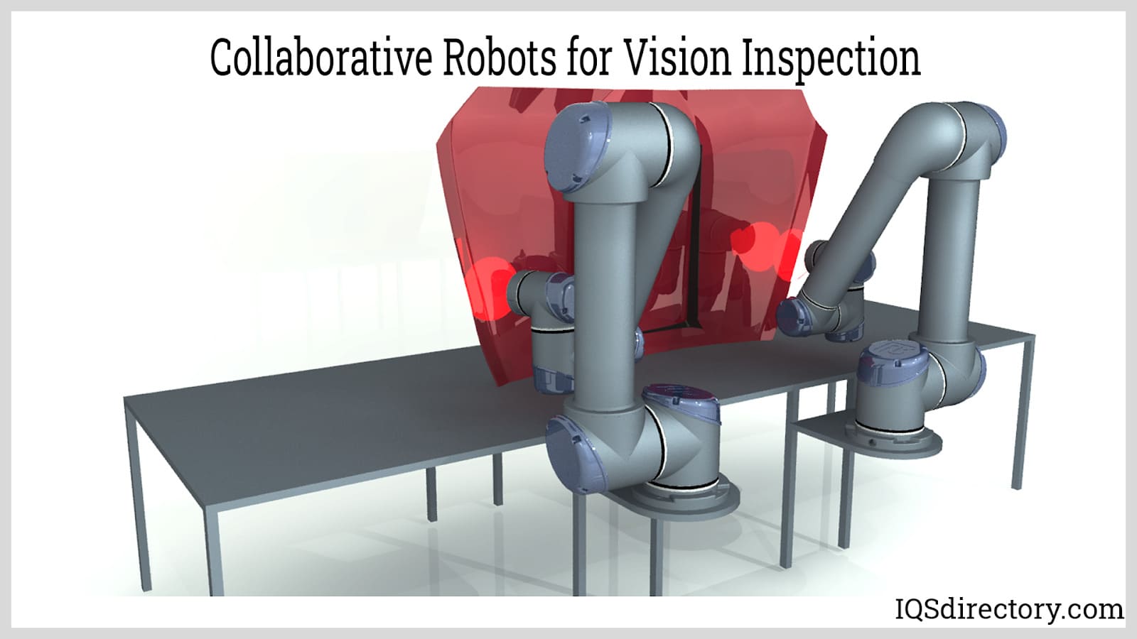
Precision and Accuracy: As previously mentioned, actuators in modern automation equipment are designed for consistent, precise movement. Whether controlled by advanced PLCs or embedded control systems, these actuators maintain accuracy in each cycle, allowing for micron-level precision in processes such as micro-assembly and electronics manufacturing. Automation technologies also enable automatic calibration and real-time error correction using sensor feedback and adaptive controls. This translates into fewer defects and less material waste.
Additional Benefits: Automation facilitates scalability in production, enabling manufacturers to quickly adapt to changing market demands. Integration with ERP (Enterprise Resource Planning) and MES (Manufacturing Execution Systems) allows seamless management across the entire supply chain. Modern automated systems also support remote monitoring and predictive maintenance, reducing unexpected downtime and enhancing overall equipment effectiveness (OEE). Companies embracing automation are better positioned to achieve digital transformation and maintain a competitive edge in the global marketplace.
Considerations for Decision-Makers: When evaluating whether to automate, manufacturers should assess their specific production needs, anticipated volume, skill requirements, and long-term business strategy. Factors like system integration capabilities, upgradability, and supplier support are vital for extracting maximum value from automation investments. Engaging experienced system integrators and automation consultants is highly recommended for achieving optimal results and future scalability.
An automation system is a complex network of interconnected devices and control architecture designed to perform tasks with minimal human intervention. The essential components of an automation system include input devices such as sensors or human-machine interfaces (HMIs), a computing system (sometimes referred to as the programmable logic controller (PLC) or industrial controller), and output elements known as manipulators or actuators that execute physical actions. These foundational elements collectively enable automated machinery and industrial automation equipment to operate efficiently in manufacturing, process industries, and robotics applications.
Among these components, the control system—which can be hardware-based (like a PLC) or software-based—serves as the system’s “brain.” There are two primary types of control systems: open-loop and closed-loop (or feedback) control. In an open-loop control system, the controller sends instructions to the actuator based solely on pre-programmed input, without monitoring real-time results, making it suitable for straightforward, repetitive automation tasks. On the other hand, a closed-loop system employs a feedback signal generated by a sensor that measures the actuator’s response—directly or indirectly—enabling continuous comparison between the actual output and desired output. The controller then dynamically adjusts commands, ensuring precision, efficiency, and process stability, which are especially critical in advanced robotic automation systems and smart manufacturing environments.
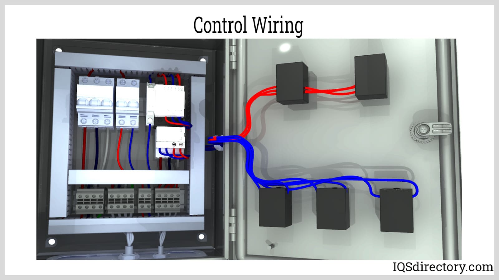
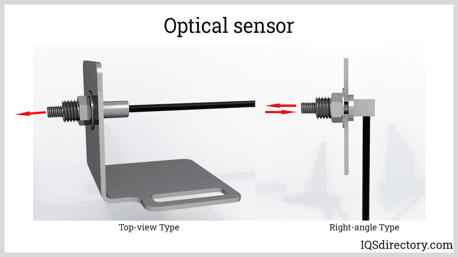
The input devices serve as the primary interface for automation systems. These include human-machine interfaces (HMIs)—touchscreens, control panels, or software dashboards—that enable operators to enter setpoints, commands, or override automated routines. Sensors (e.g., proximity sensors, temperature transducers, pressure gauges, optical sensors) are critical for real-time process monitoring. They detect or measure an array of physical and electromagnetic properties, such as temperature, pressure, position, magnetism, radiation, or fluid levels. These data are converted into electrical signals transmitted to the controller, forming the backbone of real-time industrial process control. By using advanced sensor technologies within automation, manufacturers can achieve higher accuracy, improved quality assurance, and effective predictive maintenance.
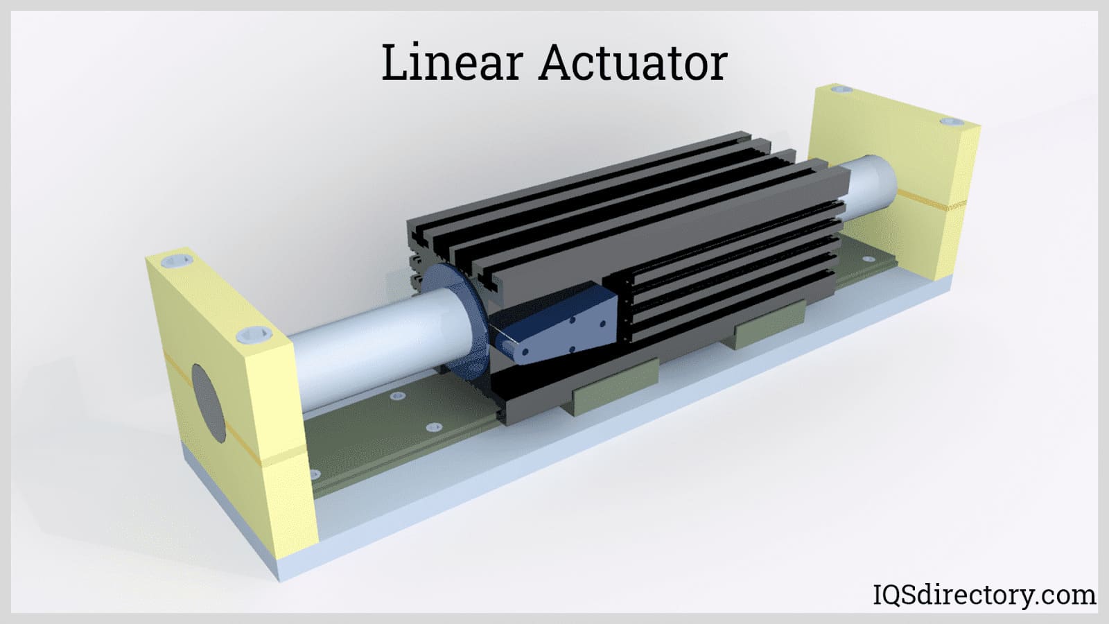
The actuator is a vital output device that translates control signals into mechanical movement. A typical actuator is comprised of a driver mechanism (such as an electric motor or solenoid) and a mechanical assembly of joints and links. The driver generates the required force or torque to actuate the linked components. Actuators are categorized by their driving force:
The mechanical system’s links (rigid structural elements) and joints enable the motion and positioning of the manipulator’s “arm.” Degrees of freedom (DOF) describe the independent movements allowed, with three translational (up-down, left-right, forward-backward) and three rotational (pitch, yaw, roll) axes. To optimize cost, complexity, and maintenance, most industrial robots and automation arms restrict joints to one or two degrees of freedom per axis or linkage. This careful design maximizes application suitability and reduces break points in automated manufacturing environments.
The robotic arm or manipulator is the core of many industrial automation systems and is designed to mount different end-of-arm tooling (EOAT) such as grippers, welders, or sensors. The arm’s configuration—defined by the combination of links and joints—impacts its range, flexibility, and application in automated manufacturing, assembly lines, and material handling. Joints are typically classified as either revolute (rotational) or prismatic (linear), influencing the arm’s degrees of freedom and workspace geometry. Proper selection of arm architecture is essential in robotics integration to optimize efficiency, precision, and suitability for task-specific automation.
Cartesian Robot: A Cartesian robot consists exclusively of three prismatic (linear) joints aligned with the X, Y, and Z axes of the Cartesian coordinate system. This architecture simplifies motion control and programming, making it ideal for precise pick-and-place operations, CNC machinery, and 3D printing. Movements are restricted to right angles, making Cartesian robots perfect for applications focused on linear transport with minimal rotations. For example, gantry systems and overhead palletizers use Cartesian configurations for straightforward automation tasks.

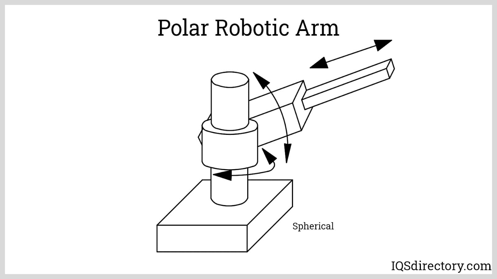
Polar Robotic Arm (Spherical Robot): Polar robots feature two revolute (rotating) joints and one prismatic (linear) joint, generating a spherical working envelope. The arm can extend or contract along its prismatic section and swing within a spherical radius, making it suitable for tasks requiring broad, sweeping motion—such as die casting, welding, and heavy component placement. The unique geometry allows for easy reach into and around complex workspaces.
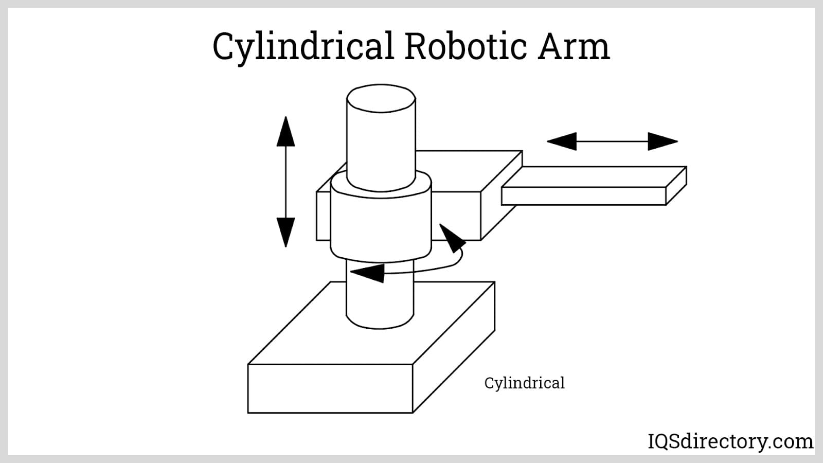
Cylindrical Robotic Arm: Differentiated by one revolute joint at the base and two prismatic joints, cylindrical arms produce a cylindrical work envelope. The rotation at the base and linear adjustment along the Z-axis and the radius provide excellent stacking, loading, and precision assembly capabilities. This design is commonly used in packaging, electronics assembly, and machine tending.
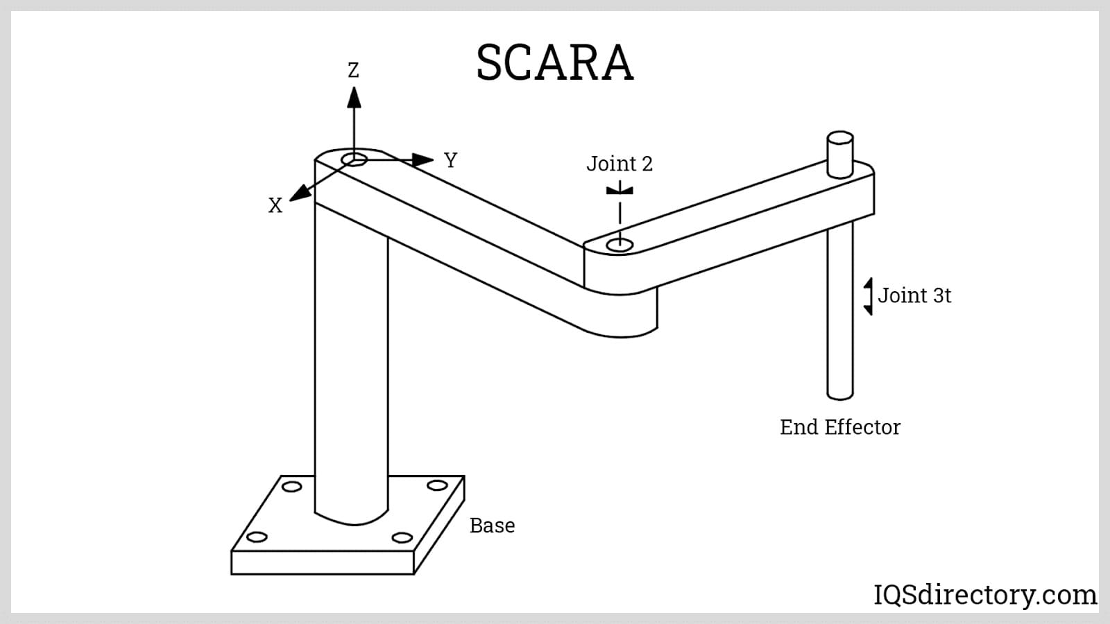
Selective Compliance Articulated Robot Arm (SCARA): The SCARA robot is optimized for tasks requiring horizontal compliance (flexibility) but vertical rigidity. With two parallel rotary joints for extension and folding in the X-Y plane, and a rigid Z-axis, SCARA robots offer fast, precise assembly and pick-and-place motions common in electronics and pharmaceutical automation. Their selective compliance is ideal for inserting components on circuit boards and packaging delicate goods without sacrificing speed or accuracy.
Articulated or Anthropomorphic Robot Arm: An articulated robot resembles the dexterity and freedom of a human arm, employing multiple revolute joints and often exceeding four or five degrees of freedom. The increased DOF allows for highly flexible movement, enabling tasks in welding, painting, and complex part assembly. Articulated arms are commonly used in automotive manufacturing, precision machining, and any automation scenario demanding intricate manipulation of objects in 3D space.
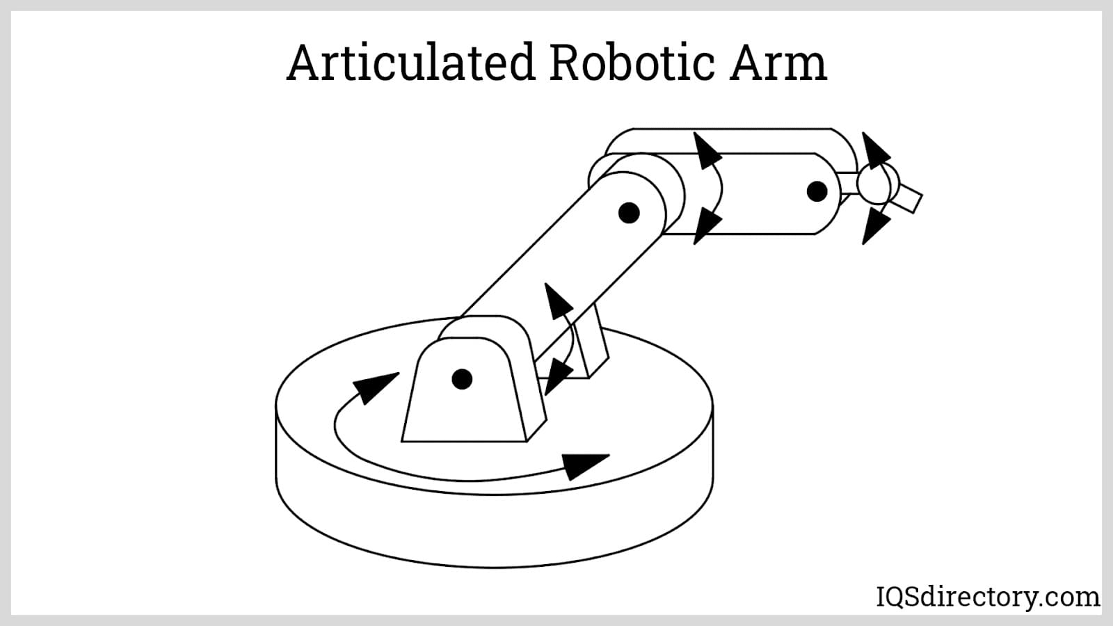
When selecting or designing an automation system, it’s essential to consider factors such as the complexity of the required motion, payload capacity, speed requirements, and environmental conditions. Different automation solutions—be it industrial robots, collaborative robots (cobots), or specialized handling systems—offer unique advantages in terms of efficiency, safety, and scalability. By understanding the interplay between input sensors, control systems, actuators, and mechanical design, businesses can optimize their automation solutions and future-proof their manufacturing operations for Industry 4.0 and smart factory integration.
An automation system uses sensors, control elements, and actuators to perform tasks with minimal or no human intervention, automating manual processes like drilling, cutting, and welding through integrated mechanical, electrical, and electronic systems.
Core components include input devices (sensors, HMIs), a control system (typically a PLC or industrial controller), and output elements such as actuators or manipulators that carry out physical operations. Sensors enable real-time feedback and process control.
Open-loop systems execute pre-programmed instructions without real-time feedback, suitable for repetitive tasks. Closed-loop systems use sensor feedback to continuously adjust operations, ensuring precision, efficiency, and process stability in advanced automation.
Automation excels in repetitive or hazardous tasks such as assembling, welding, packaging, cutting, inspecting, and process control. These systems are commonly used in manufacturing, electronics, packaging, and heavy-duty industrial applications.
Advantages include consistent production, high repeatability, precision, increased quality, improved working conditions, and lower operating costs. Disadvantages are high initial investment, added maintenance needs, and reduced versatility in adapting to new tasks.
Robotic arms use combinations of rotary (revolute) and linear (prismatic) joints, resulting in Cartesian, polar, cylindrical, SCARA, or articulated layouts. The configuration affects range, flexibility, speed, and application suitability in automation tasks.
End-of-arm tools (EOATs), also known as end effectors, are the components designed to interact with products or processes. Most EOATs are grippers, which handle objects by lifting, dropping, transferring, or reorienting them. Grippers can employ various methods for handling objects and are classified as impactive (mechanical jaws), ingressive (needles), astrictive (vacuum and magnetism), and contigutive (adhesion). Additionally, EOATs can be customized for specific tasks such as milling or welding.
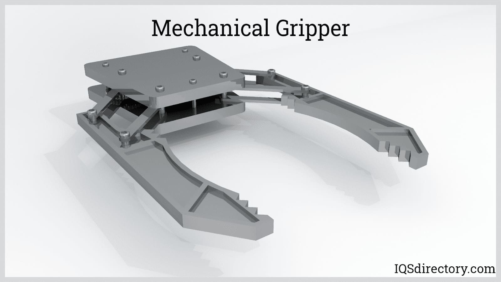
Mechanical Grippers: These are used for basic pick-and-place robotic systems. Grippers have one to three sets of mechanical jaws that are driven typically by servo motors or pneumatic actuators. These jaws are composed of one line which is connected to the wrist by a revolute or prismatic joint. To control the gripping force when using servo motors, feedback is generated by strain gauges or the motor current. For grippers using pneumatic actuators, the gripping force can be increased without damaging the item due to the inherent compressibility of air. The jaws can be constructed as forks, fingers, parallel plates, or surfaces following the shape of the payload. A better grip is achieved by lining the surfaces with resilient, high friction materials.
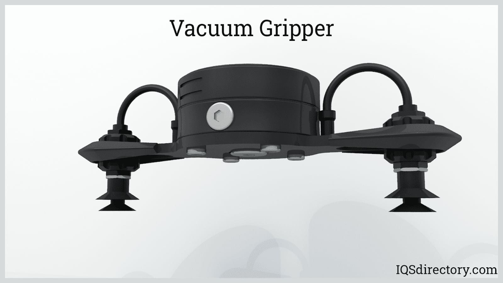
Vacuum or Suction Cups: These are used for picking objects with smooth surfaces such as films, glass, and plates. A common way of producing a vacuum is through the use of a venturi supplied with compressed air. To create a larger suction force, an array of suction cups is used. Vacuum EOATs are cleaner than mechanical grippers and can allow some positional deviation. This type of EOAT is not suitable for rough, porous, or irregular surfaces. Moreover, the object can slip out of the suction cup when accelerated too quickly.
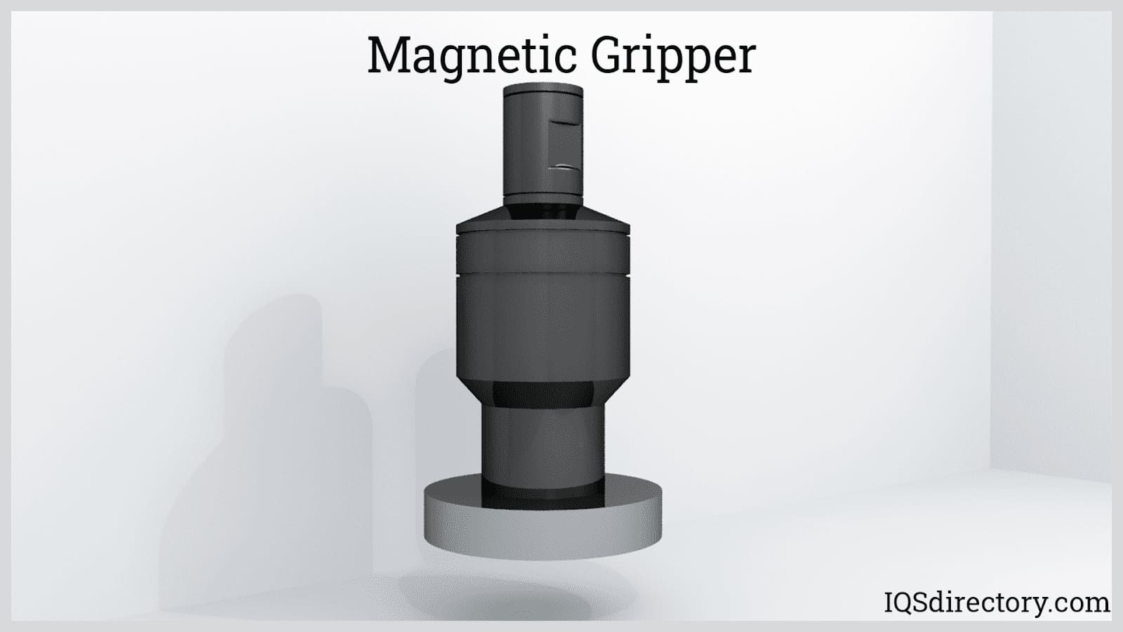
Magnetic Grippers: These types of EOATs use electromagnets for lifting ferromagnetic objects. Permanent magnets are also used since it does not continuously consume power. However, it needs a mechanical device for removing the collected object. Electromagnets are preferred due to their simple operation since the object can be lifted or dropped simply by supplying or cutting power to the electromagnet. However, aside from the limitation of its use on ferromagnetic materials, it also causes the parts to be magnetic. Also, it cannot be accelerated too quickly since the attached object can slip.
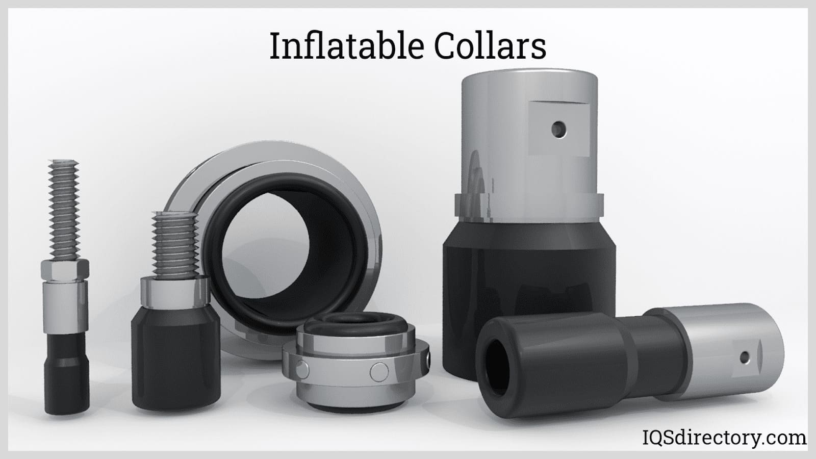
Inflatable Collars and Cylinders: An inflatable collar can be visualized as a looped elastomer tube supported by a rigid structure on its outer periphery. It grips the object by expanding the tube while releasing, which is done by deflating. These are commonly used in the two-dimensional gripping of tubular or cylindrical products.
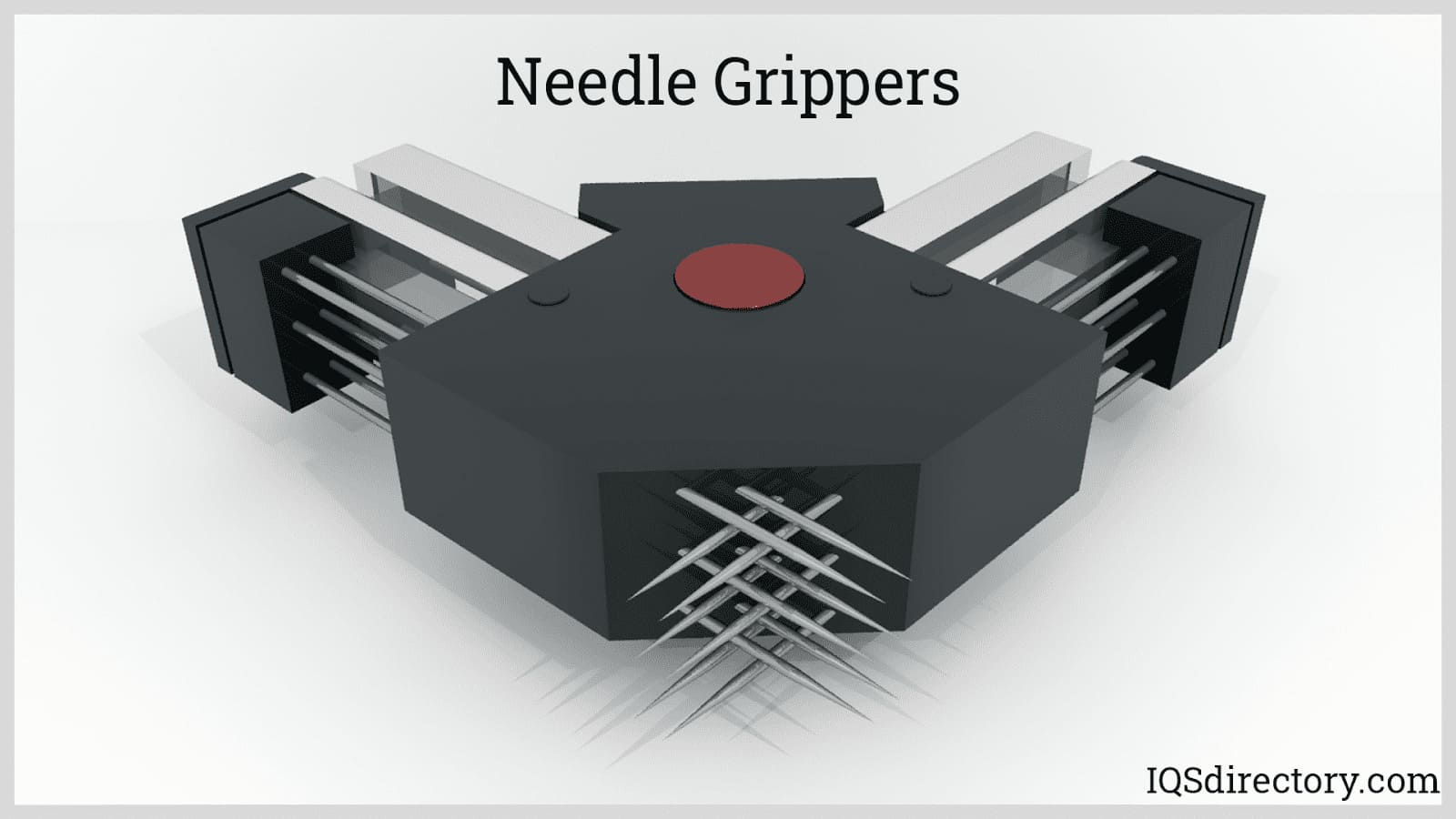
Needle Grippers: These types perform gripping action by penetrating the object or bulk with needles or hackles. These EOATs are usually static without any moving links of joints. Needle grippers are used in handling porous or fibrous objects such as textiles, carbon and glass fibers where small penetrations are not an issue.
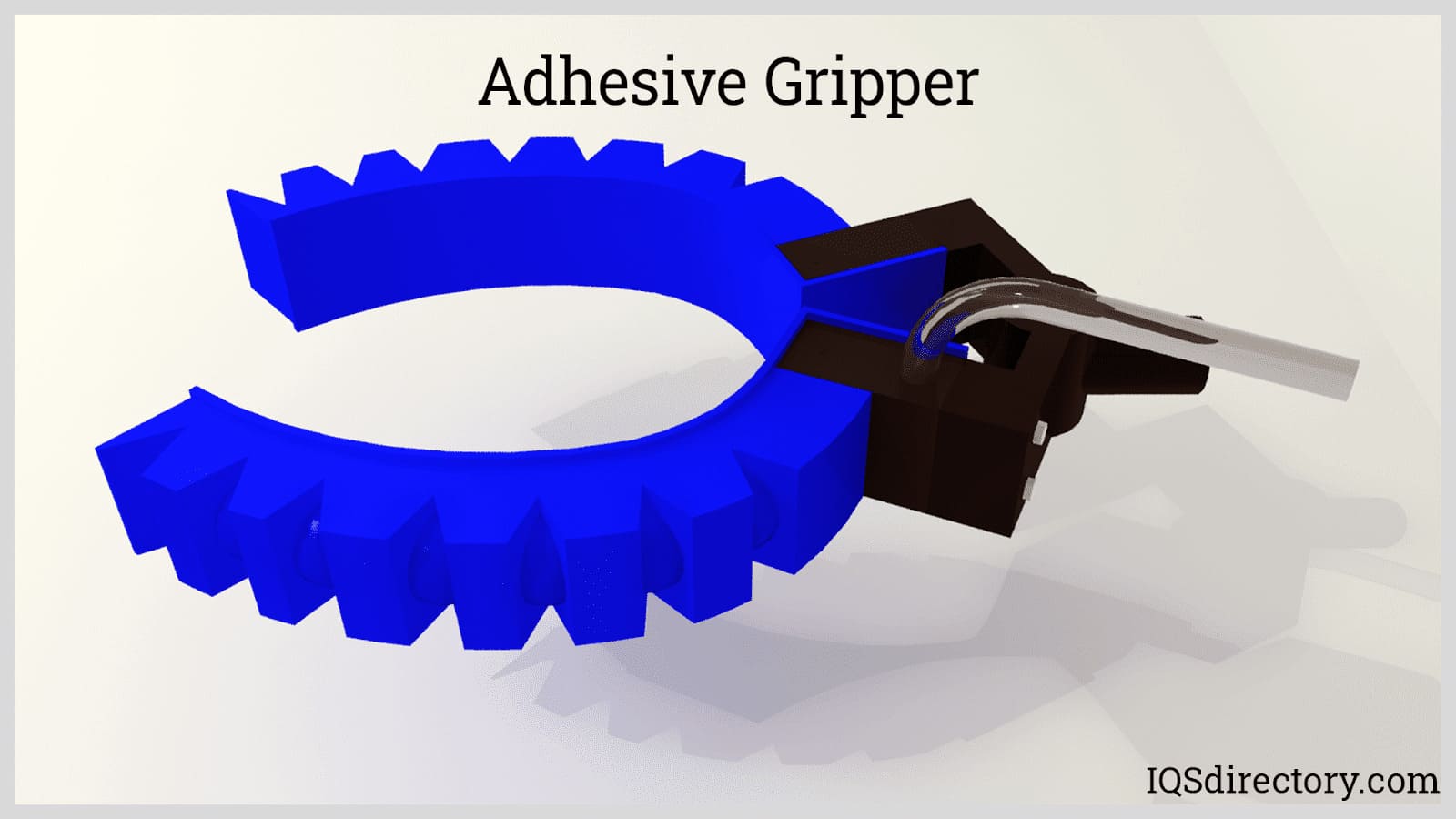
Adhesive Grippers: As the name suggests, these types of grippers grasp the product through surface adhesion. A special type of adhesive is coated onto the surface of a pad or plate which contacts the product to be lifted. The main advantage of adhesive grippers is their ability to operate without any air or power supply. However, they are limited to handling light objects and they tend to lose gripping effectiveness over time.
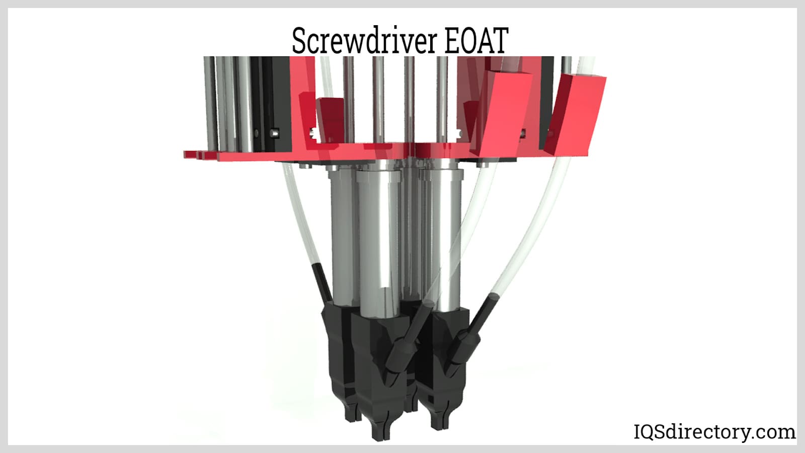
Tools (Permanent and Changeable): Tools can be fitted at the outermost link of the wrist instead of a gripper. The tool can be permanently attached or changeable. Common tools for end effectors are screwdrivers, wrenches, drills, rotating cutters, lasers, waterjet nozzles, paint spray nozzles, welding electrodes, and solders. Other specialized end effectors include inspection systems with mounted sensors. An example of this is a camera or other type of optical device which is used for non-contact testing and 3D measurements. The resulting measurements are exact in the order of tenths of a millimeter due to the intrinsic repeatability, precision, and accuracy of robotic systems.
Existing tools installed to the robotic arm can also be changed over time due to modifications brought about by new product requirements, system improvements, or part obsolescence. In deciding whether the new tool is applicable, several factors must be verified:
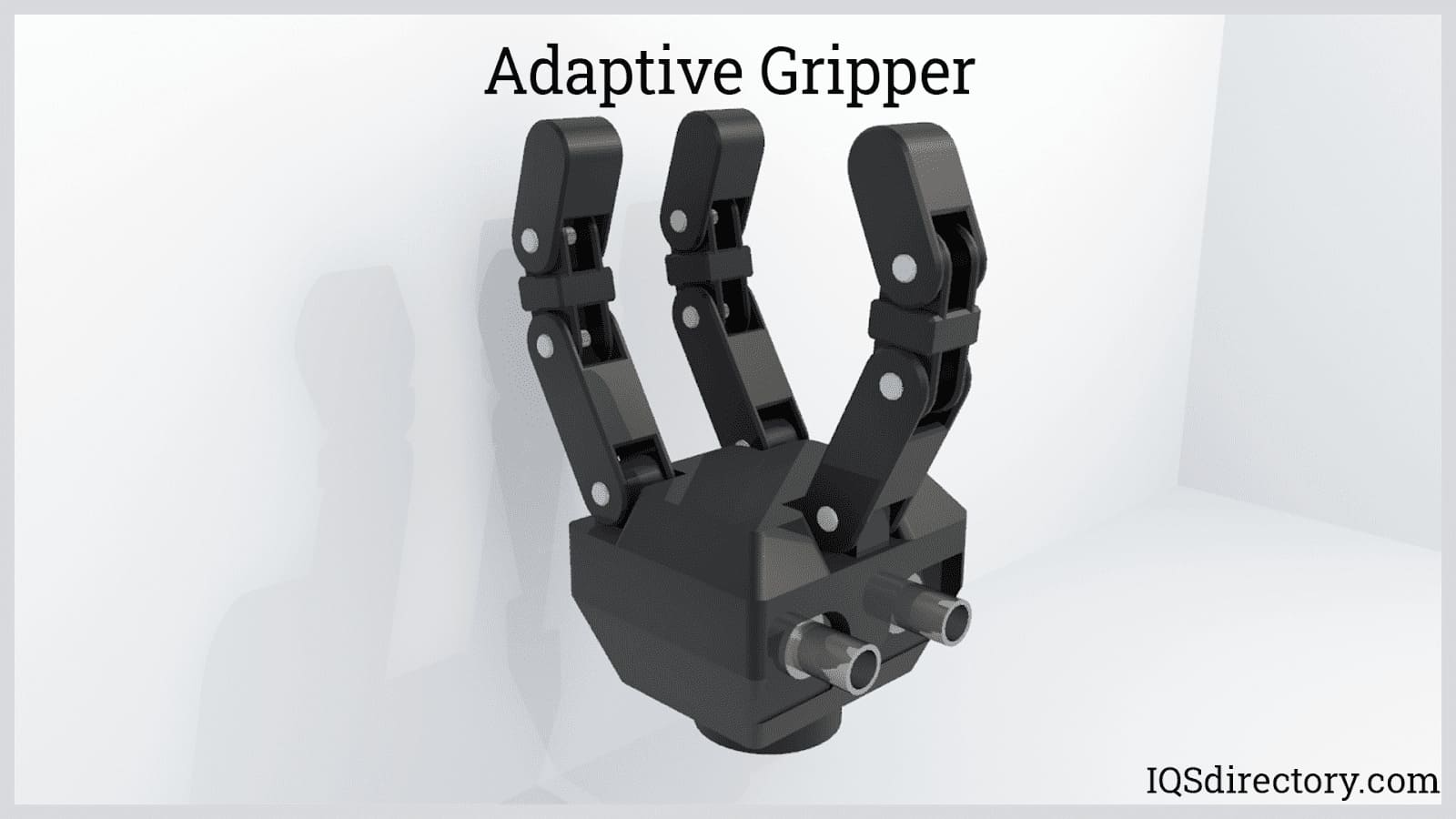
Anthropomorphic and Adaptive Grippers: In comparison with mechanical grippers, anthropomorphic grippers have more complicated links and joints. Mechanical grippers typically have one link connected to the wrist by a revolute or prismatic joint. Anthropomorphic grippers, on the other hand, have two or more links chained together by revolute joints. They can be configured to provide two- or three-dimensional gripping by having two or three sets of fingers. To be adaptive, each finger is actuated independently with mounted sensors for checking proximity and grip strength. Anthropomorphic and adaptive grippers are useful in applications where the objects are frequently varying such as in sorting and multiple product line packaging systems.
Actuators are components that supply force or torque to produce movement. They are connected to the links and joints via tendons, gears, chains, cams, or shafts, forming the core actuation system. Actuators are typically classified into three types: electric, hydraulic, and pneumatic.
Electric Actuators: Electric actuators are the most widely used actuators for industrial robots. The most common type of electric actuator is a servo motor energized by a DC power supply. The rotational movement of the motor can be converted into linear action by various mechanical transmission systems such as belts, cables, and chains. Electric actuators that create direct linear motion also exist in the form of linear motors and solenoids. The main types of electric actuators are summarized below:
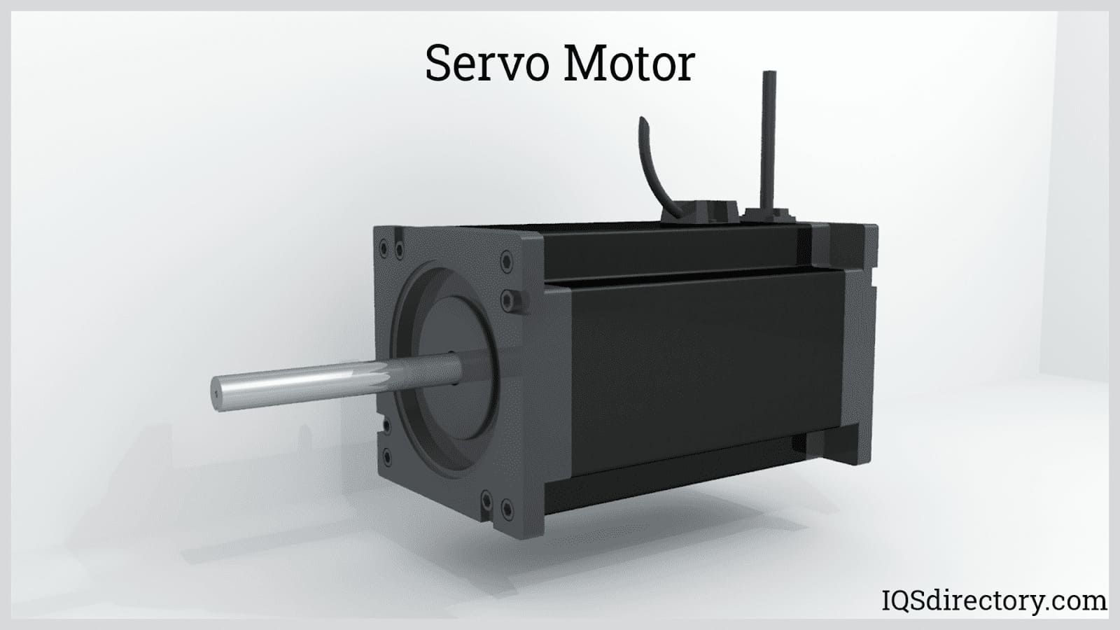
Servo motors: This type of electric actuator operates through a closed-loop or feedback system which processes an output signal to control its position, velocity, and acceleration. The motors used in the servomechanism can be a brushed DC motor, brushless DC motor, AC motors, and even linear motors. The servomechanism has a sensor, transducer, or potentiometer called an encoder that measures the position and speed of the motor and converts it into an electronic signal. The signal, either digital or analog, is fed to an amplifier and controller which then alters the voltage or frequency of the electric power supplied to the motor.
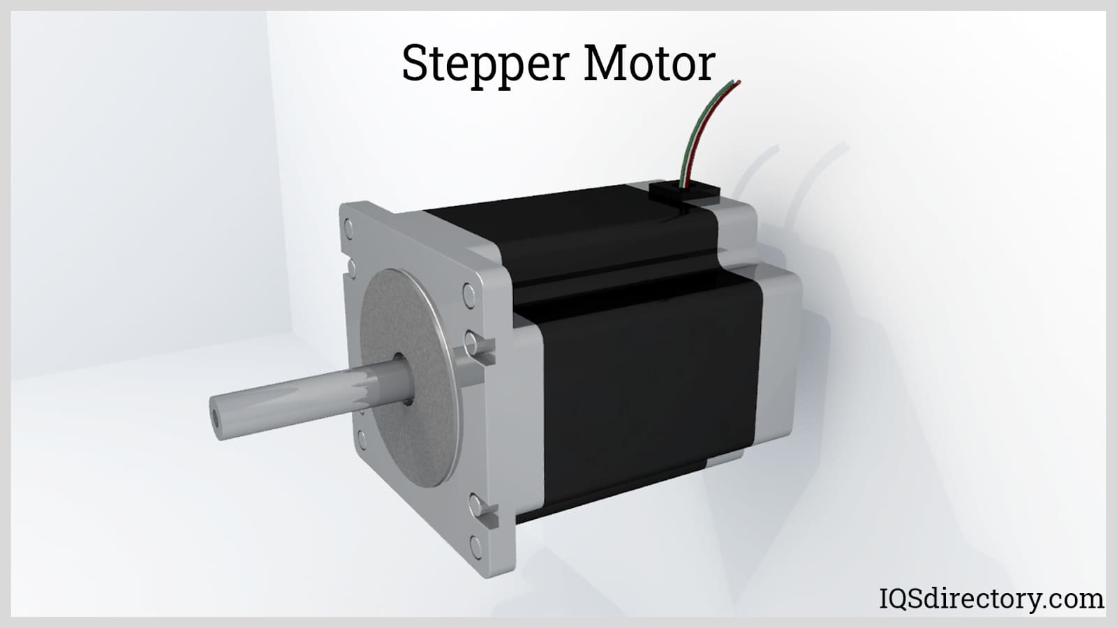
Stepper Motors: Unlike the servomotor, stepper motors do not need a feedback loop. They operate through the continuous energization and de-energization of stator poles that pull the poles of the rotor. The stator has poles energized separately to pull the rotor poles and create a stepping or indexing rotation. The rotor is made of laminated ferromagnetic material with a different number of poles than the stator. The difference in the number of poles of the rotor and the stator allows only one set or pair of poles to be attracted at a time. A controller and amplifier power the poles according to the programmed speed of the motor. Stepper motors are simpler than servo motors but are less powerful. If the load is exceeded, the motor can slip. Since there is no built-in feedback loop, there is no way to correct the deviation.
Pneumatic Actuators: Pneumatic actuators operate using compressed air typically at pressures around 6 to 10 bars. The flow of compressed air is controlled by solenoid valves. The most common types of pneumatic actuators are cylinders or rams. A pneumatic cylinder has a piston that extends or retracts upon the application of pressure inside the cylinder. One side of the piston is connected to a rod which couples to the robot arm. Other methods of coupling are also possible such as cables and magnets. The amount of force generated depends on the pressure and the effective area of the piston.
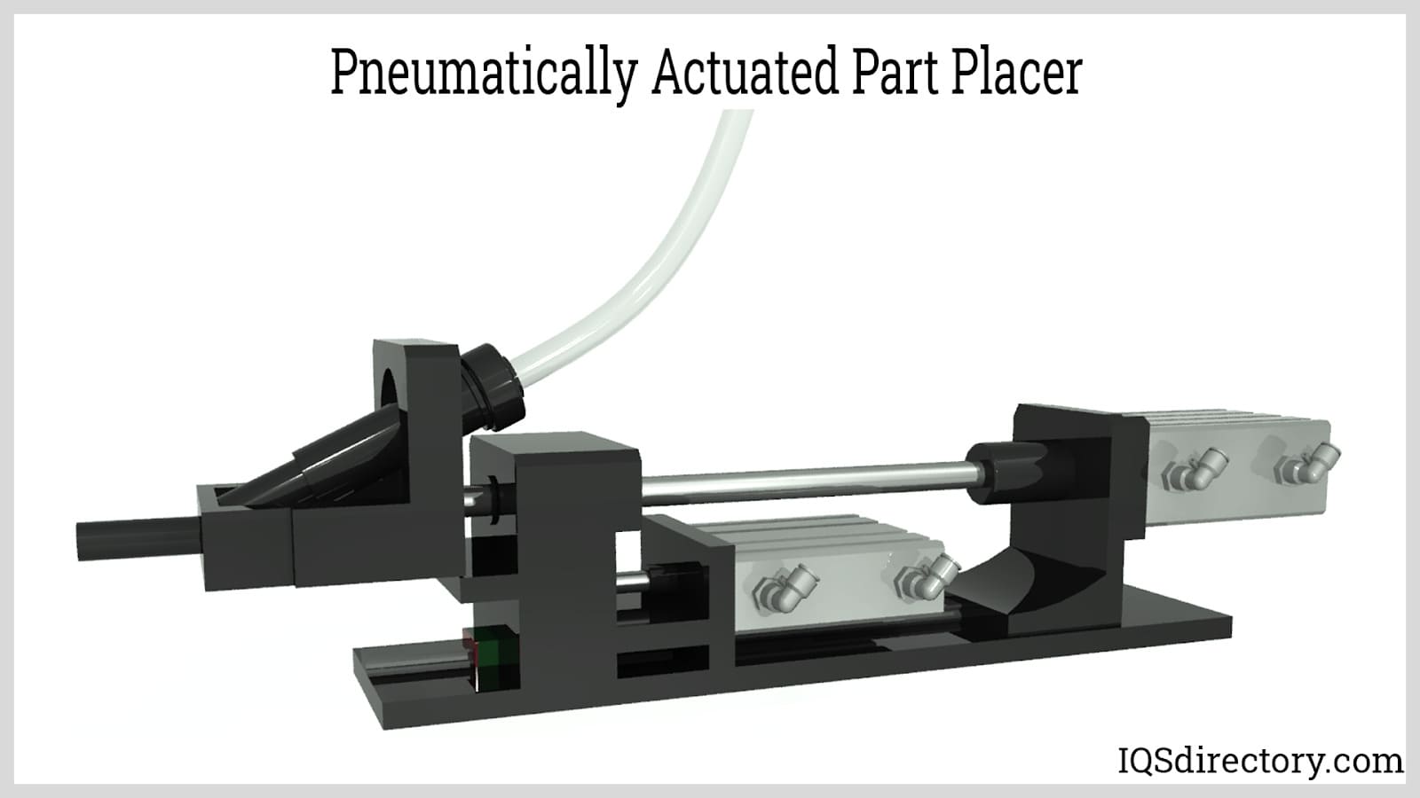
Pneumatic cylinders can be single-acting or double-acting. A single-acting cylinder has only one inlet port in which the compressed air pushes the piston in one direction only. The return stroke is achieved by an external force such as spring force or gravity. On the other hand, a double-acting cylinder has two ports on both ends of the cylinder that acts as both inlet and exhaust ports. Compressed air is supplied on one end and is released on the other. This allows the piston to move and exert force in both directions. A less common type of pneumatic cylinder is a telescoping cylinder which is composed of nested shells that extend when compressed air is introduced. Telescoping cylinders can be single or double-acting.
For creating rotary motion using compressed air, pneumatic motors are used. Common pneumatic motors are rotary vanes and turbines. Rotary vanes operate through the positive displacement of air as it passes the rotor. Turbines create rotation using the kinetic energy of the passing air. Aside from pneumatic cylinders and motors, other types of pneumatic actuators exist such as tubes, bellows, and diaphragms. Though different in construction, they function the same way as cylinders and motors.
Hydraulic Actuators: Hydraulic actuators operate the same way as pneumatic actuators. The only differences are the magnitude of force created, the robustness of construction, its fluid circuit, and the ability to be servo-controlled. Hydraulic actuators can exert very large forces suited for carrying heavy payloads. This can be attributed to the incompressibility of hydraulic fluids or oil. Pressures can go as high as 130 bars. Because of the high pressures involved, hydraulic actuators are constructed with very thick and rigid metals. The rams and pistons are surface treated and sealed to prevent any fluid leakage.
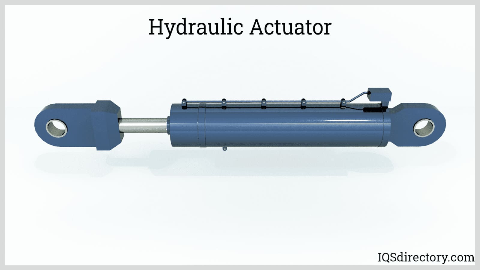
Pneumatic circuits are typically open where the air is not recirculated within the system. In hydraulic circuits, the fluid is returned to the pumping unit where oil is filtered and cooled before recirculation. When compressed at very high pressures, the fluid tends to heat up which can accelerate its degradation.
Another desirable characteristic of hydraulic actuators is their ability to be servo-controlled. Pneumatic cylinders are only capable of fully extending or retracting. Hydraulic cylinders, on the other hand, are capable of being servo-controlled in which their extension length and speed can be precisely controlled.

An automatic screwdriver is a piece of equipment that automatically inserts screws into a product during assembly and production. Since every production operation is unique and requires a...
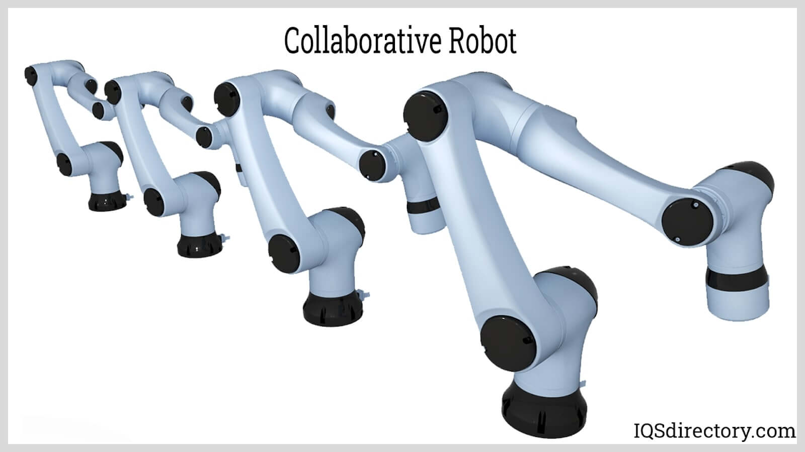
Collaborative robots, also abbreviated as Cobots, are the newest technology in robotics. They have changed the automation world significantly. These robots can work safely together with workers, hence are...
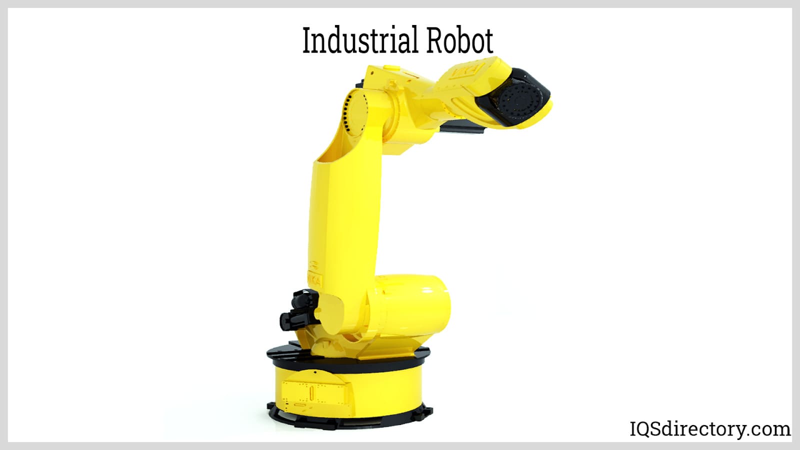
An industrial robot is an autonomous system of sensors, controllers, and actuators that executes specific functions and operations in a manufacturing or processing line. They operate continuously through repetitive...
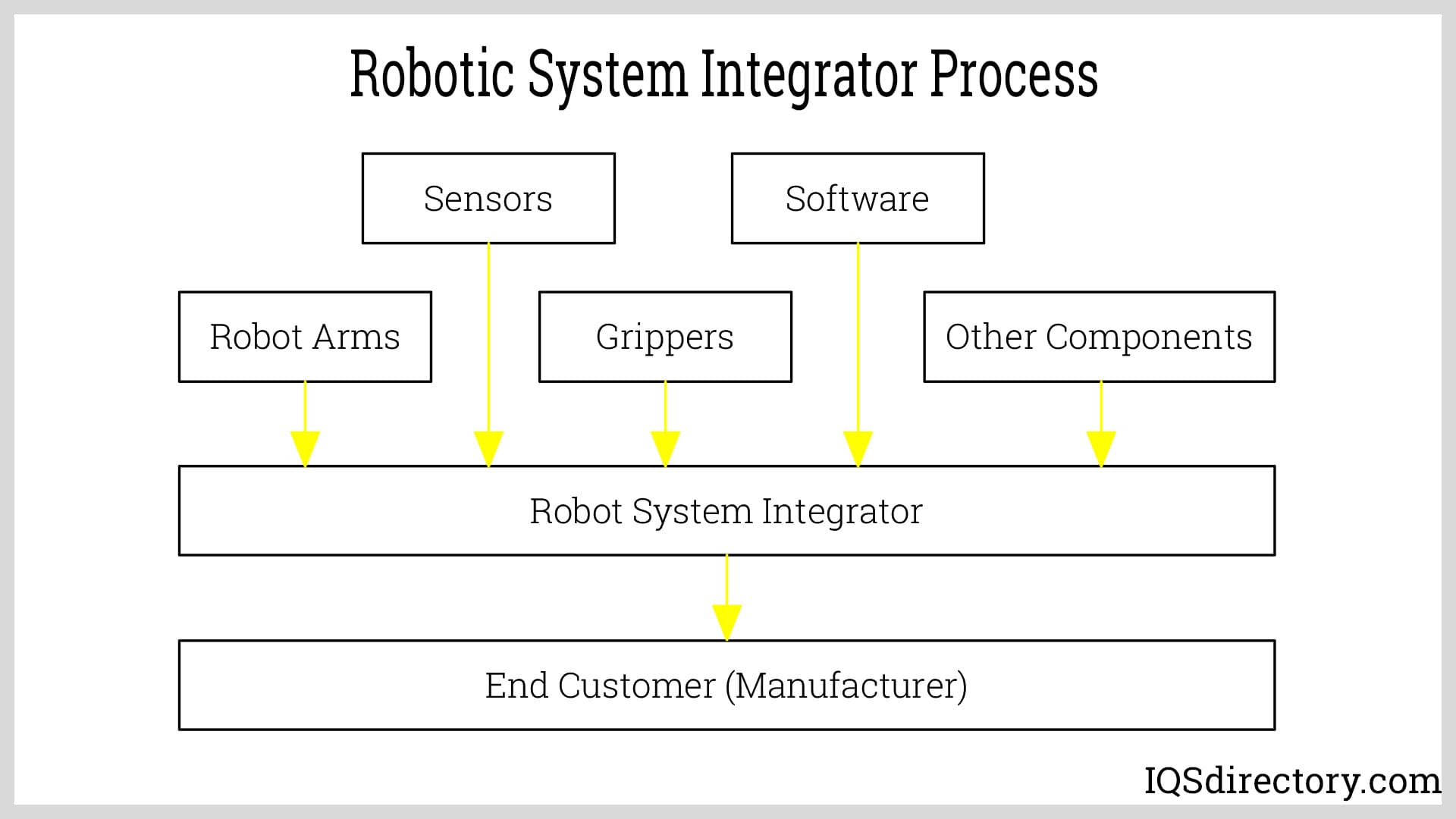
Robotic system integrators are companies that provide assistance in automating a wide range of applications. They help design robotic technologies that best suit the needs of an operation for a company and solutions as...
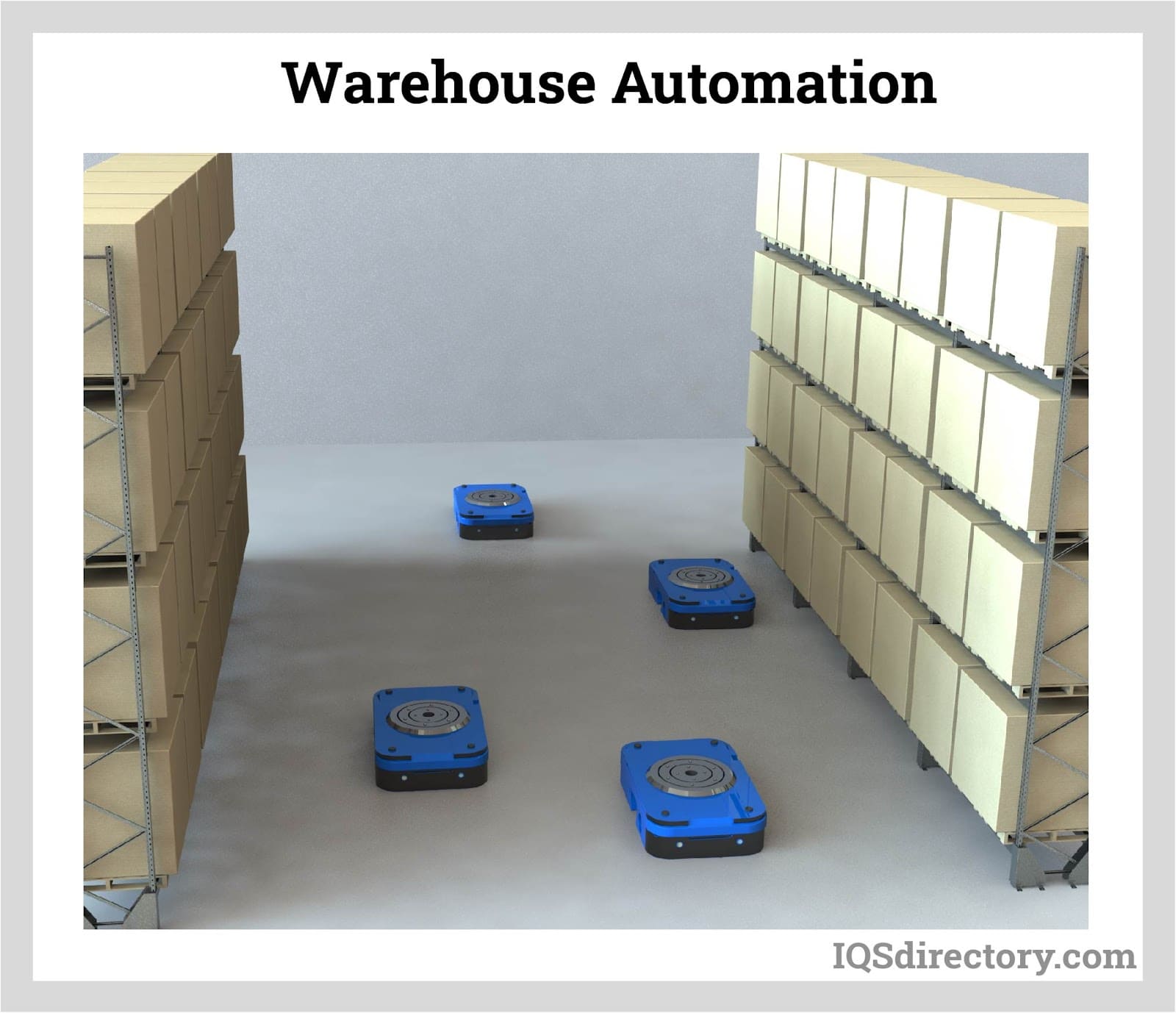
Warehouse automation is the process of replacing repetitive tasks with systems that are automated. The main goal is to remove labor-intensive duties that consume time. As a result, the workers can focus more on...
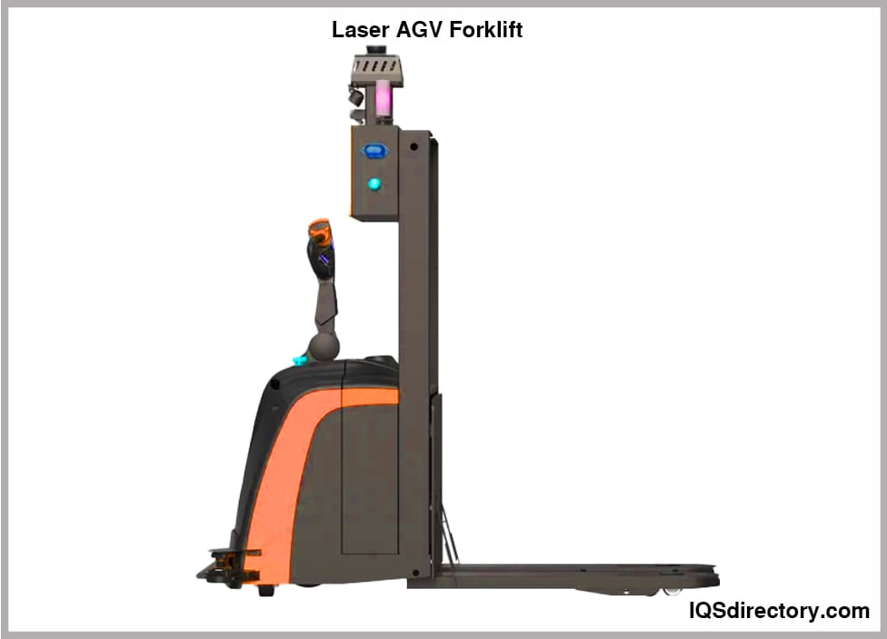
An AGV forklift is a driverless self-operating robotic device that has the ability to carry, lift, retrieve, and place loads for easy transfer from one location to another. An automatic guided vehicle (AGV) forklift is a computer controlled mechanism that...
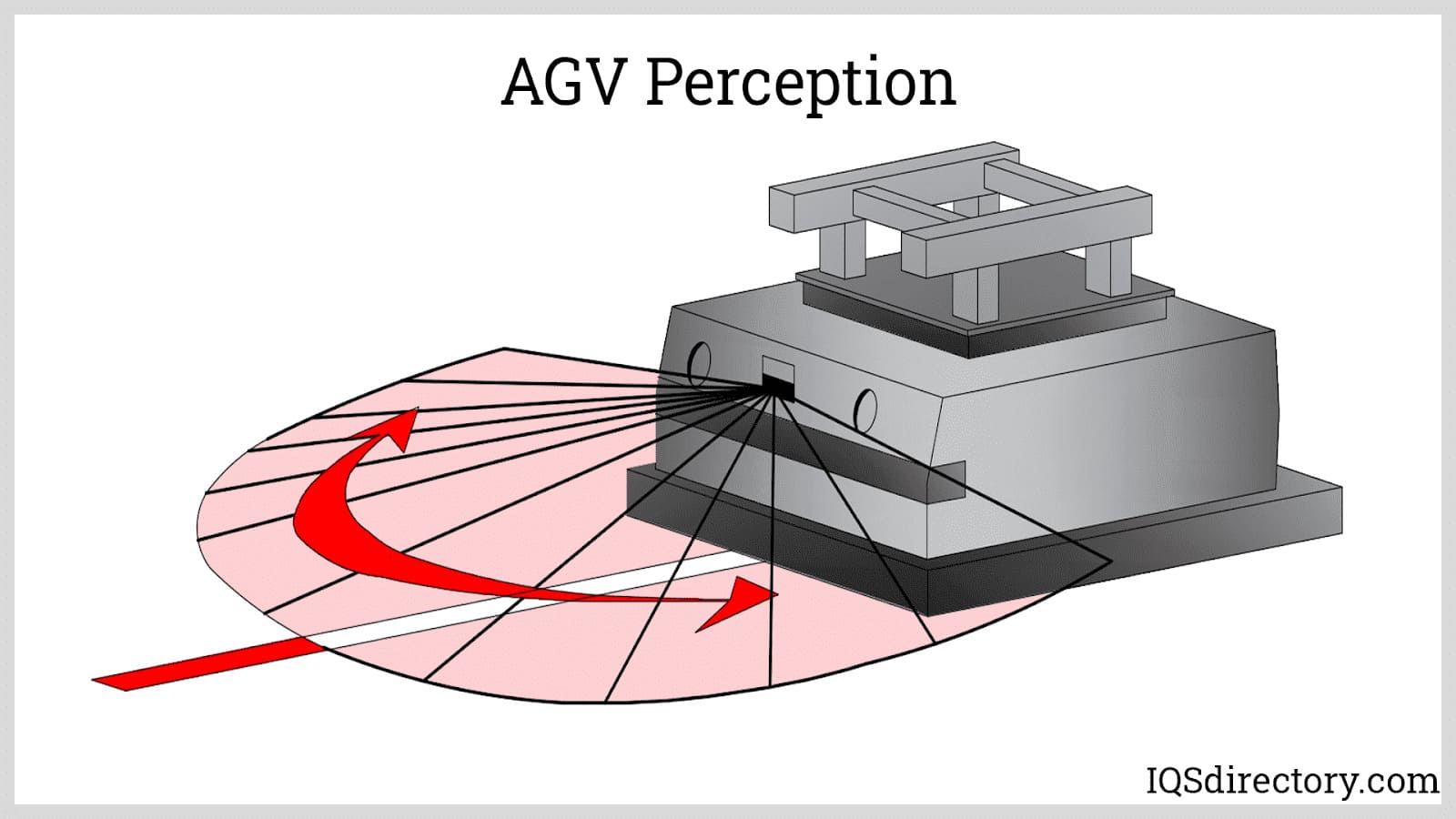
Automated guided vehicles (AGV) or mobile robots are types of guided robotic systems that are not bounded by a fixed range of motion. Rather, it is self-contained and can move along a line, surface, or space...
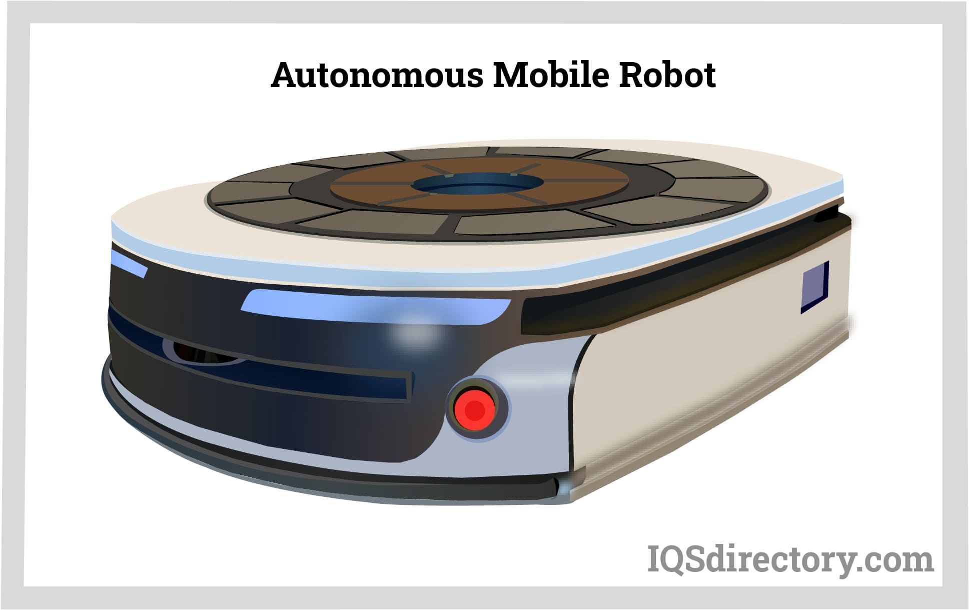
An autonomous mobile robot (AMR) is a self-propelled self-powered mechanism designed to perform repetitive tasks or organizational functions using an internal guidance system. They are able to navigate their...
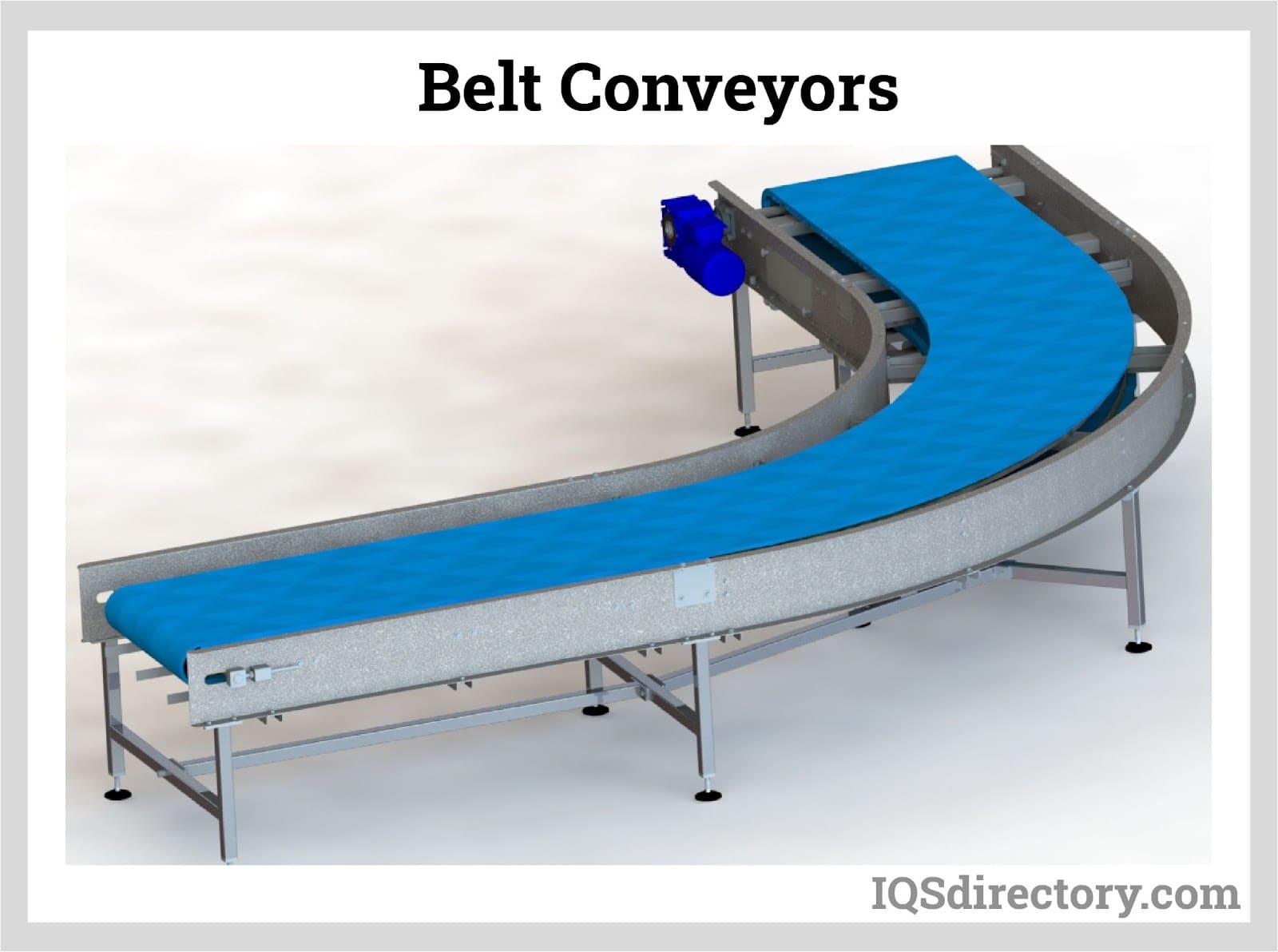
A belt conveyor is a system designed to transport or move physical items like materials, goods, even people from one point to another. Unlike other conveying means that employ chains, spirals, hydraulics, etc...
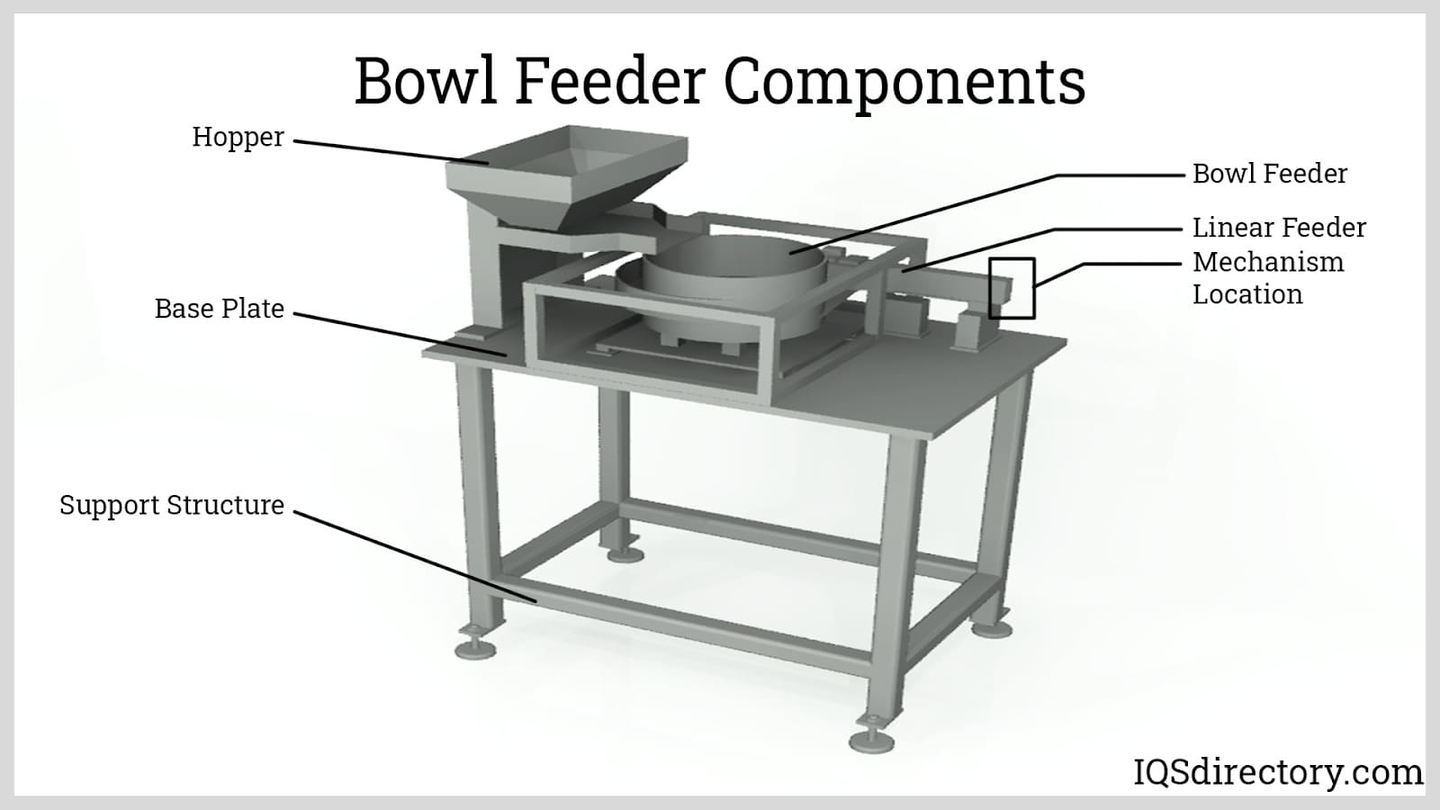
A bowl feeder is a mechanism for supplying small parts and components to a production line or for sorting bulk items for rapid use. A self contained bowl feeder system has a bowl that sets on a spring loaded base that moves vertically...
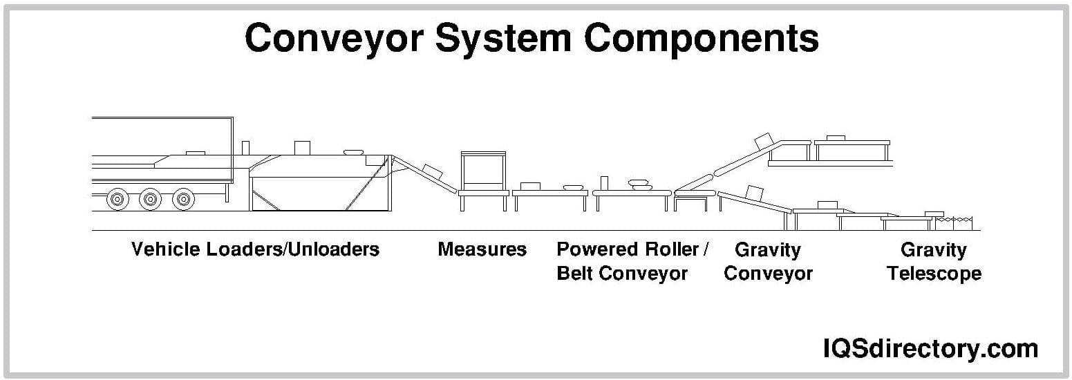
A conveyor system is a method for moving packages, products, supplies, parts, and equipment for production, shipping, or relocation. The different types of conveying systems include pneumatic, screw, belt, and roller. The construction of individual systems depends on the materials...
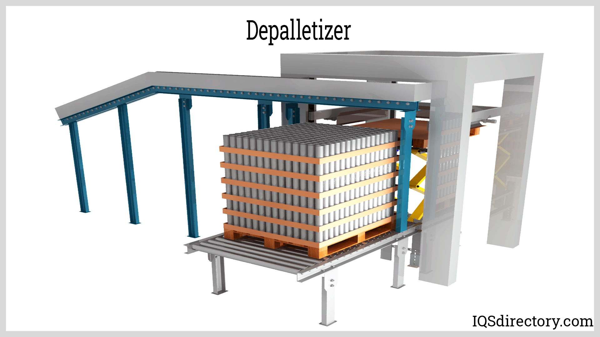
Palletizing is the process of putting items on a pallet. The process of emptying the loaded objects in the reverse pattern is known as depalletizing. A pallet is a flat, square-shaped platform used to transport and...
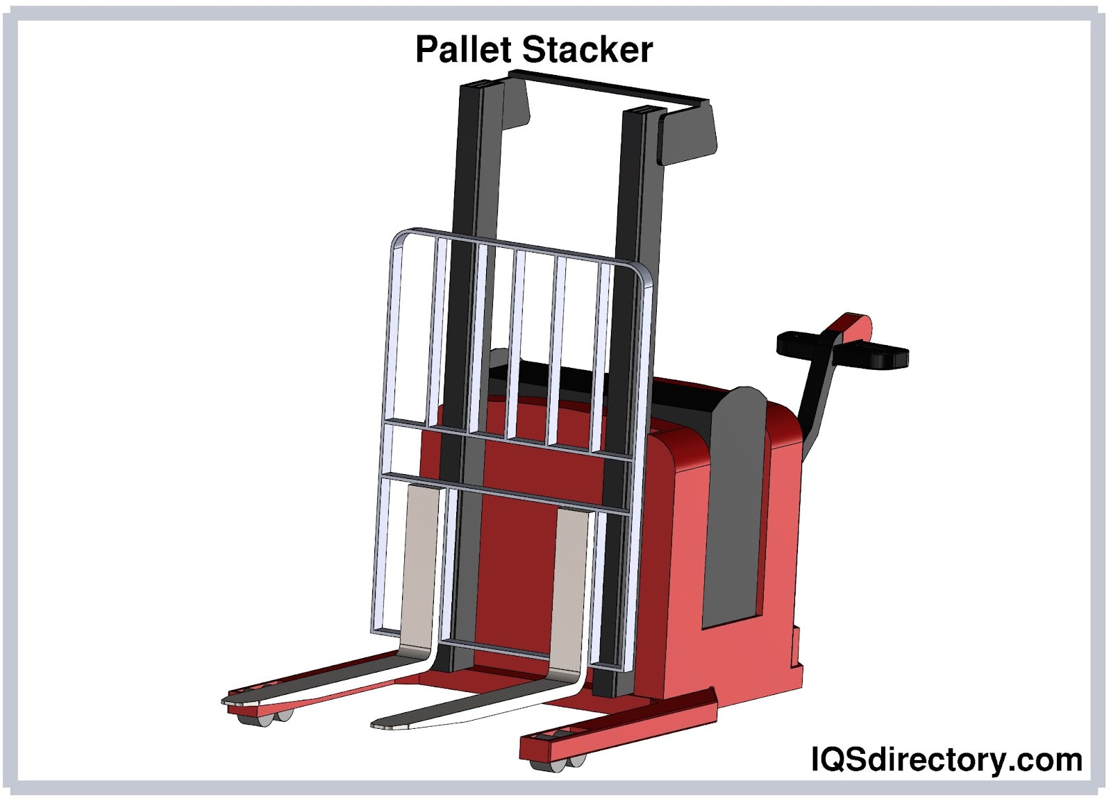
A pallet stacker is a machine designed to assist the user in lifting, moving and handling palletized materials with ease. A pallet itself is a flat and horizontal structure used to support goods in a sturdy fashion...
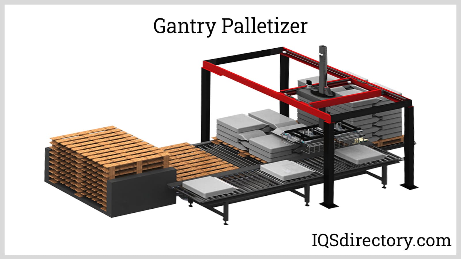
A palletizer is an automated material handling machine used to stack and orient several individual products into a single load for a more convenient and economical method of handling, storage, and shipment. Palletizers are usually part of a bigger packaging process...
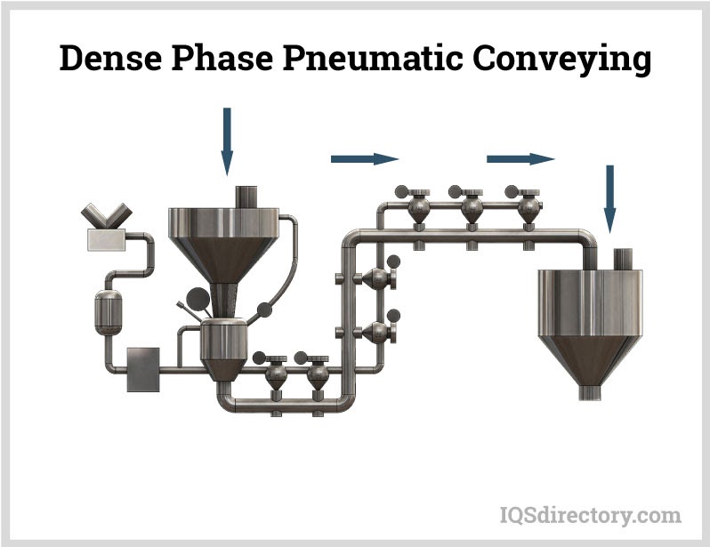
Pneumatic conveying is a method for transferring bulk materials, like powders and granules, using compressed gas or air, from one processing center to another. Material is moved through an enclosed conveying line or tube using a combination of pressure differential and airflow from a blower or fan...
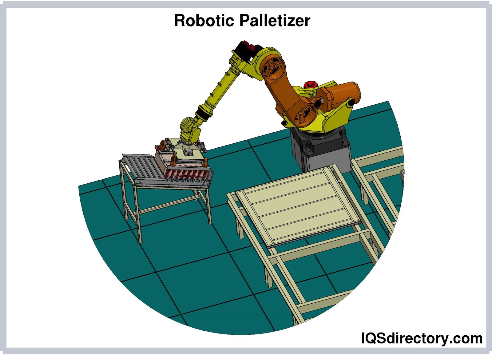
A robotic palletizer is a type of palletizer that employs a robotic arm to pick, orient, and place individual products and arrange them into a single stack of load. They are the next generation of palletizers, and they will supersede conventional palletizers...
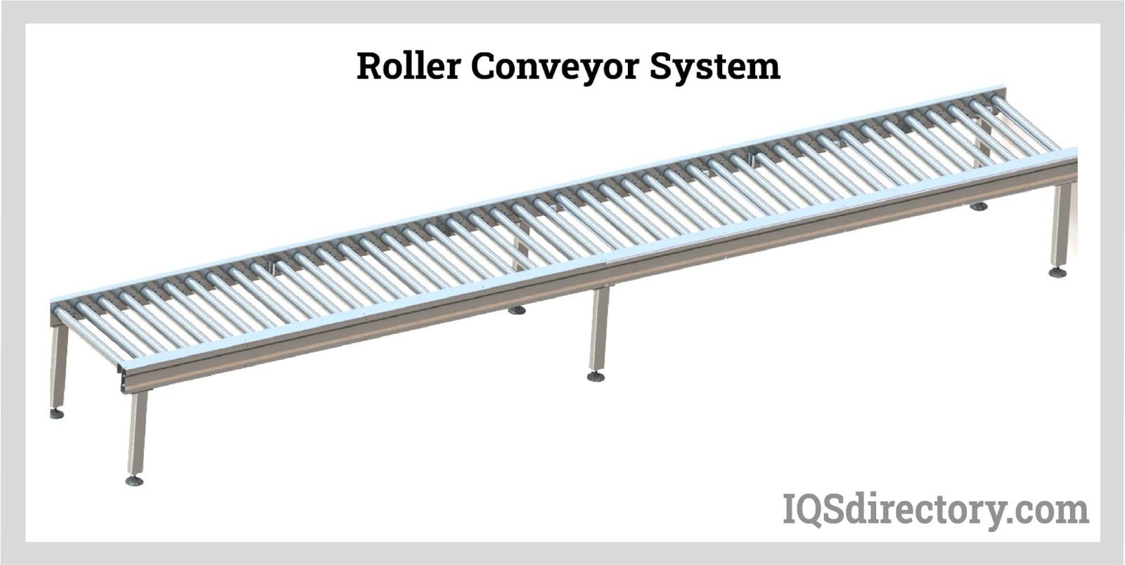
Roller conveyors are a type of conveyor belt that allows objects to skate on its surface by using rollers, which are equally spaced revolving cylinders. They transport stuff from one location to another...
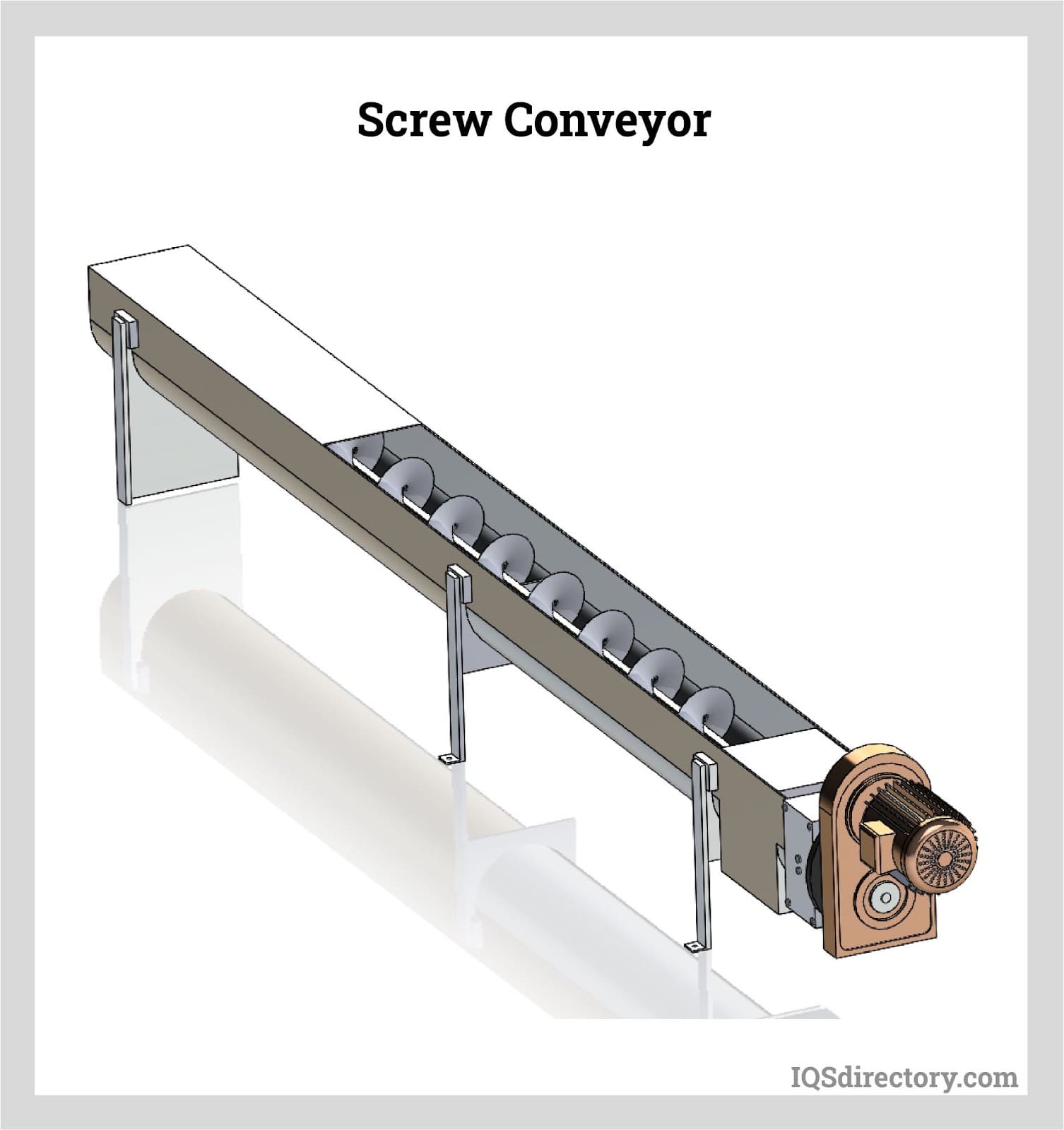
Screw conveyors, or auger conveyors, are industrial equipment used in transporting bulk quantities of granular solids (e.g., powder, grains, granules), semi-solids, liquids, and even non-flowing materials from one point to another...
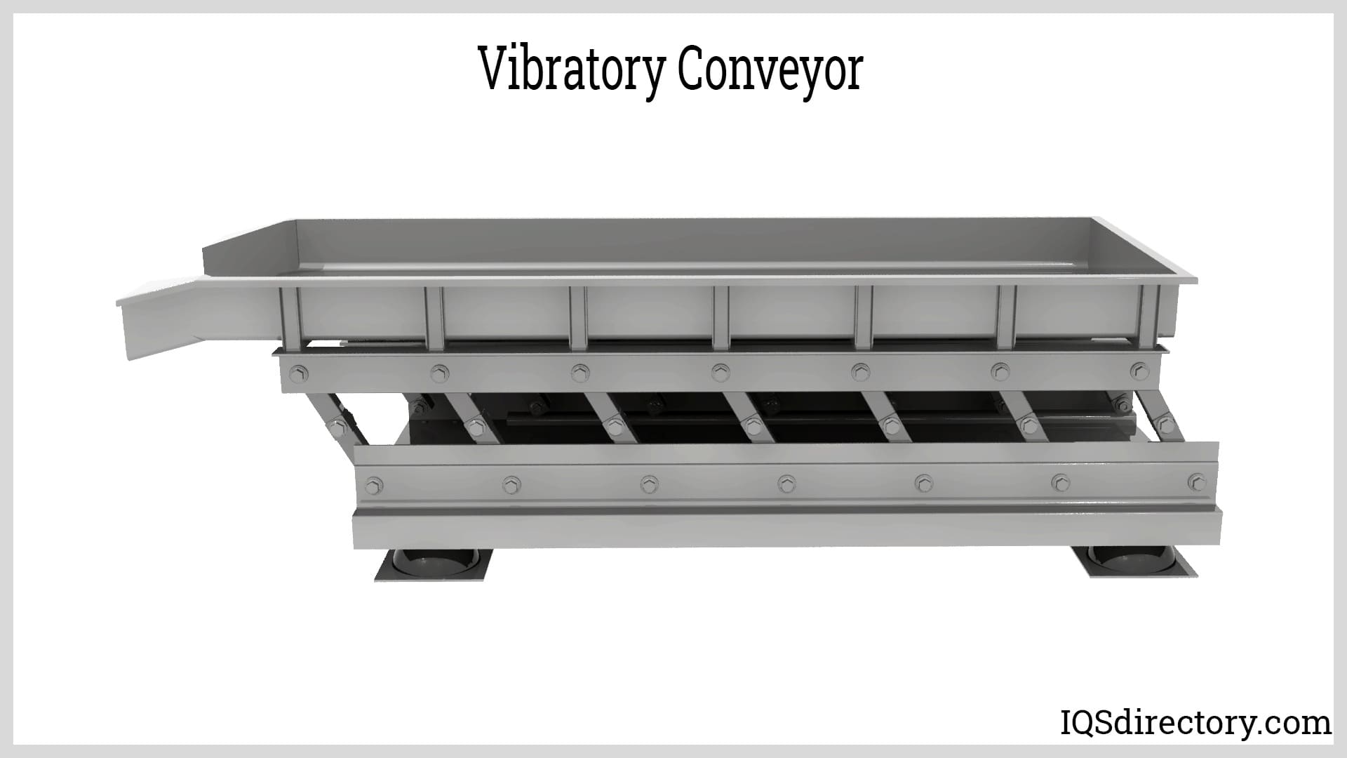
Vibratory conveyors are material-handling equipment used to transport fine to coarse-grained bulk materials. These vibratory conveyors are strong conveying equipment utilized for bulk commodities with fine to coarse graininess...
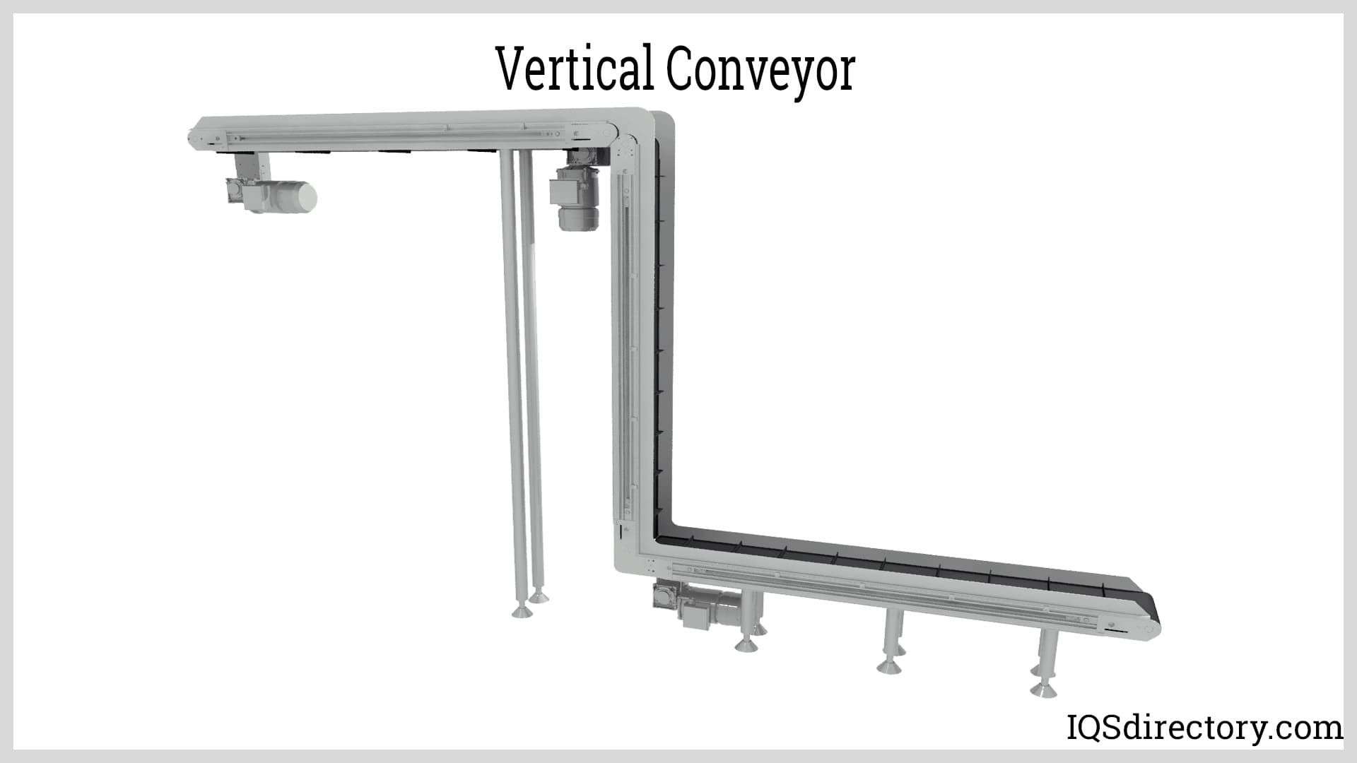
A vertical conveyor is an engineered mechanical method for moving goods, products, supplies, parts, and components from a lower level to a higher level or from a higher level to a lower level. They are...
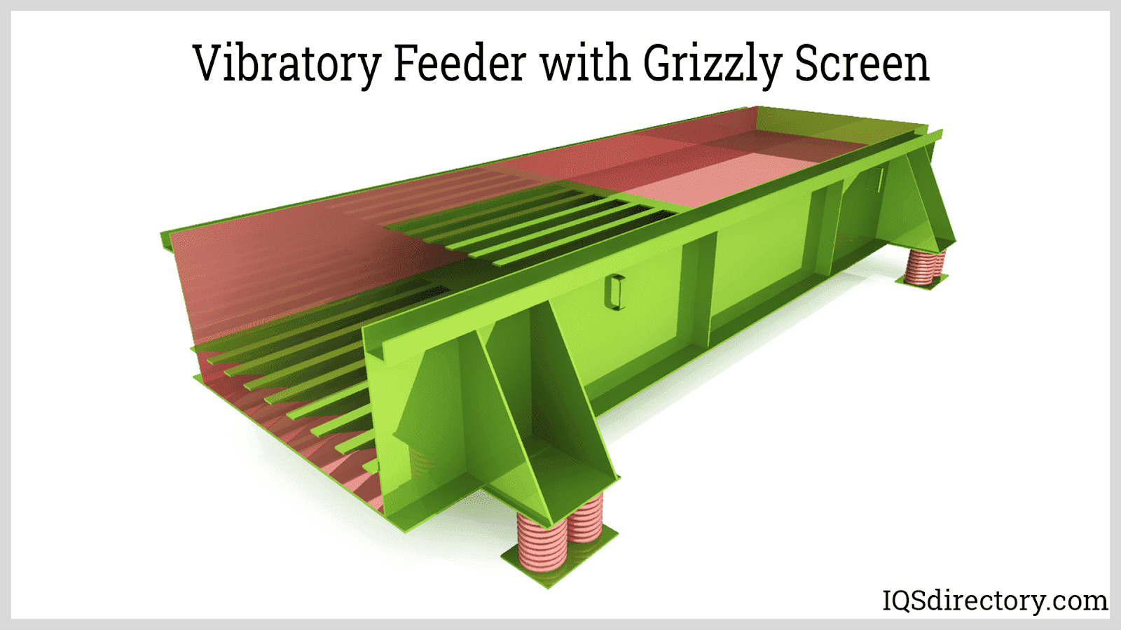
Vibratory feeders are short conveyors used to transport bulk materials utilizing a controlled vibratory force system and gravity. The vibrations impart a combination of horizontal and vertical acceleration through tossing, hopping, or sliding-type of action to the materials being handled...
In 1954, when Arthur "Mac" Barrett, of Barrett Electronics Corporation, unveiled the first AGV, he named it Guide-o-Matic and described it as a driverless vehicle...