Screw Machined Parts and Products
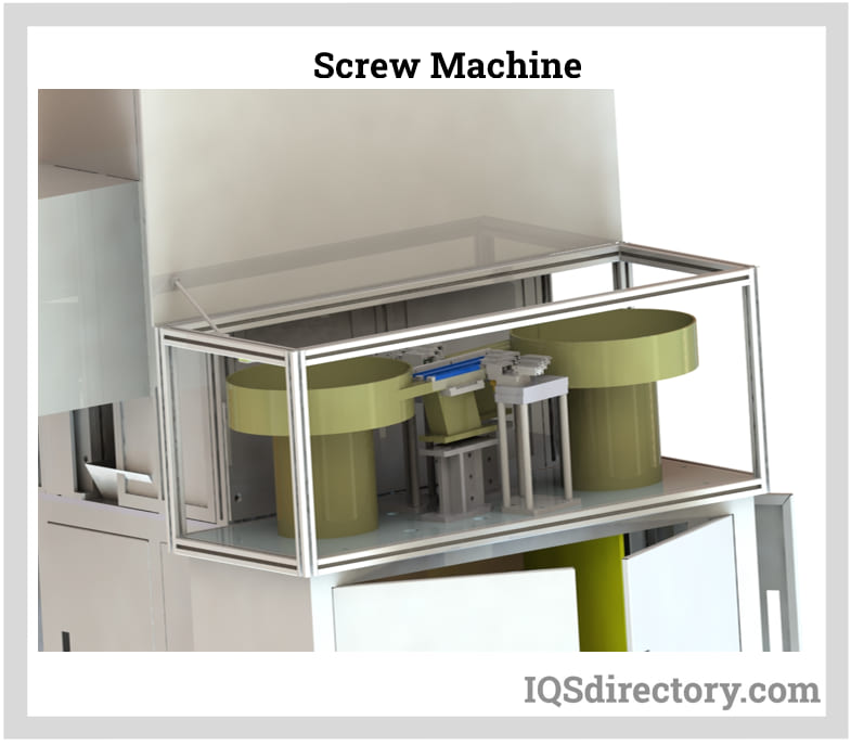
Screw machined parts are complex pieces that are typically cylindrical and threaded and a screw machined product is a family of automatic lathes for small to medium-sized components...
Please fill out the following form to submit a Request for Quote to any of the following companies listed on
This guide contains everything you need to know about thread rolling and screw machine products.
You will learn about topics such as:
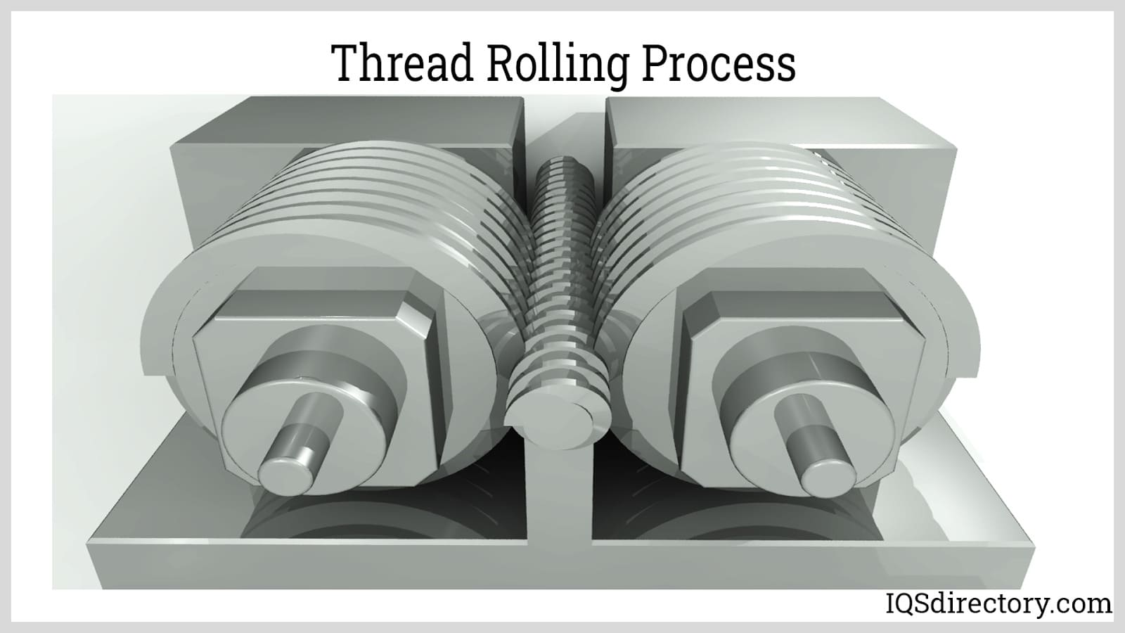
Thread rolling is a threading process that involves deforming metal stock by pressing it between dies to produce external threads on the surface. This technique can also generate internal threads via a procedure known as thread forming. Unlike conventional threading methods like thread cutting, thread rolling is a non-subtractive approach, meaning it doesn't involve removing metal from the stock. Rolled threaded fasteners offer benefits such as enhanced thread strength, accurate final measurements, superior surface finish, and reduced friction coefficients.
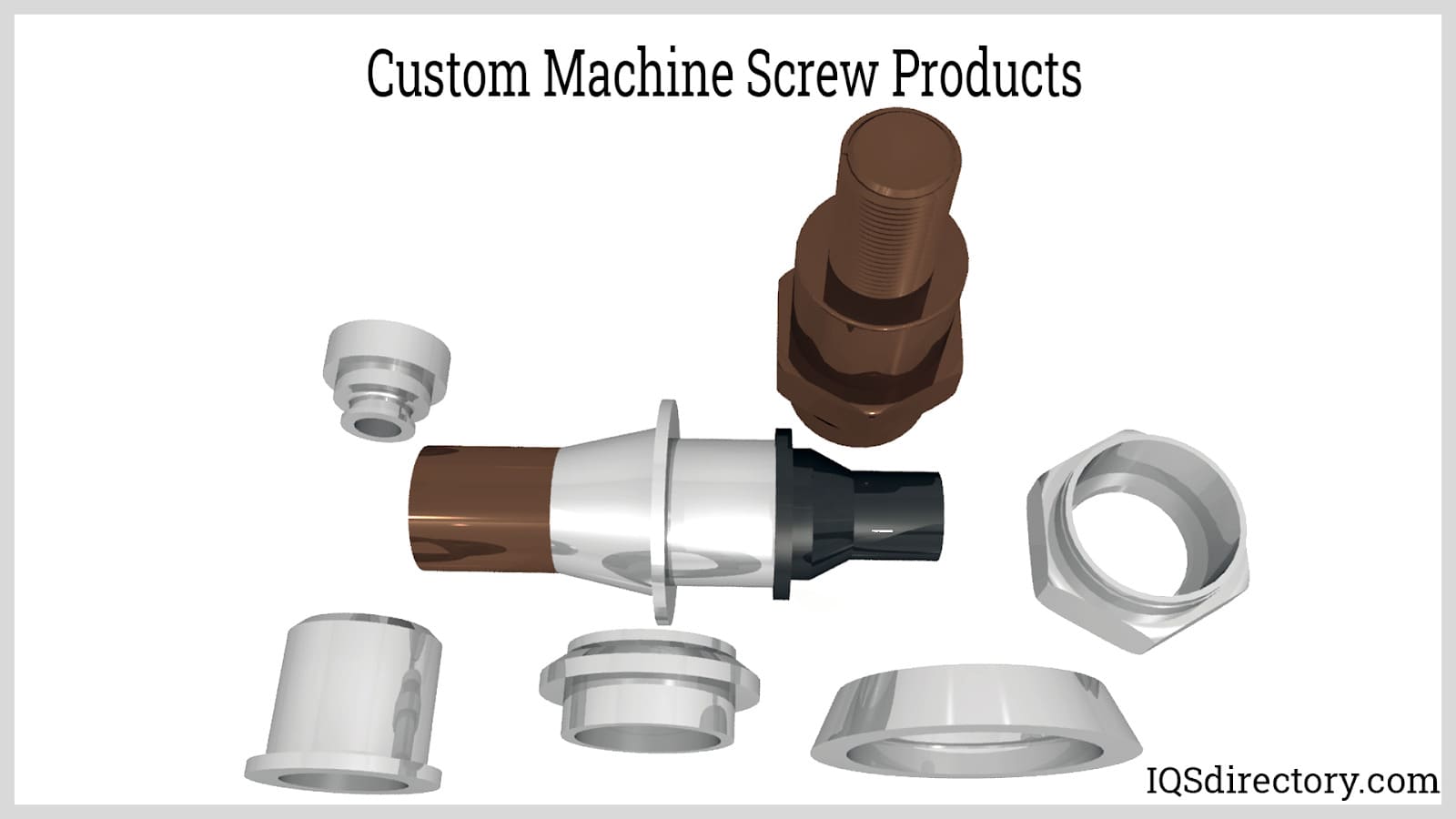
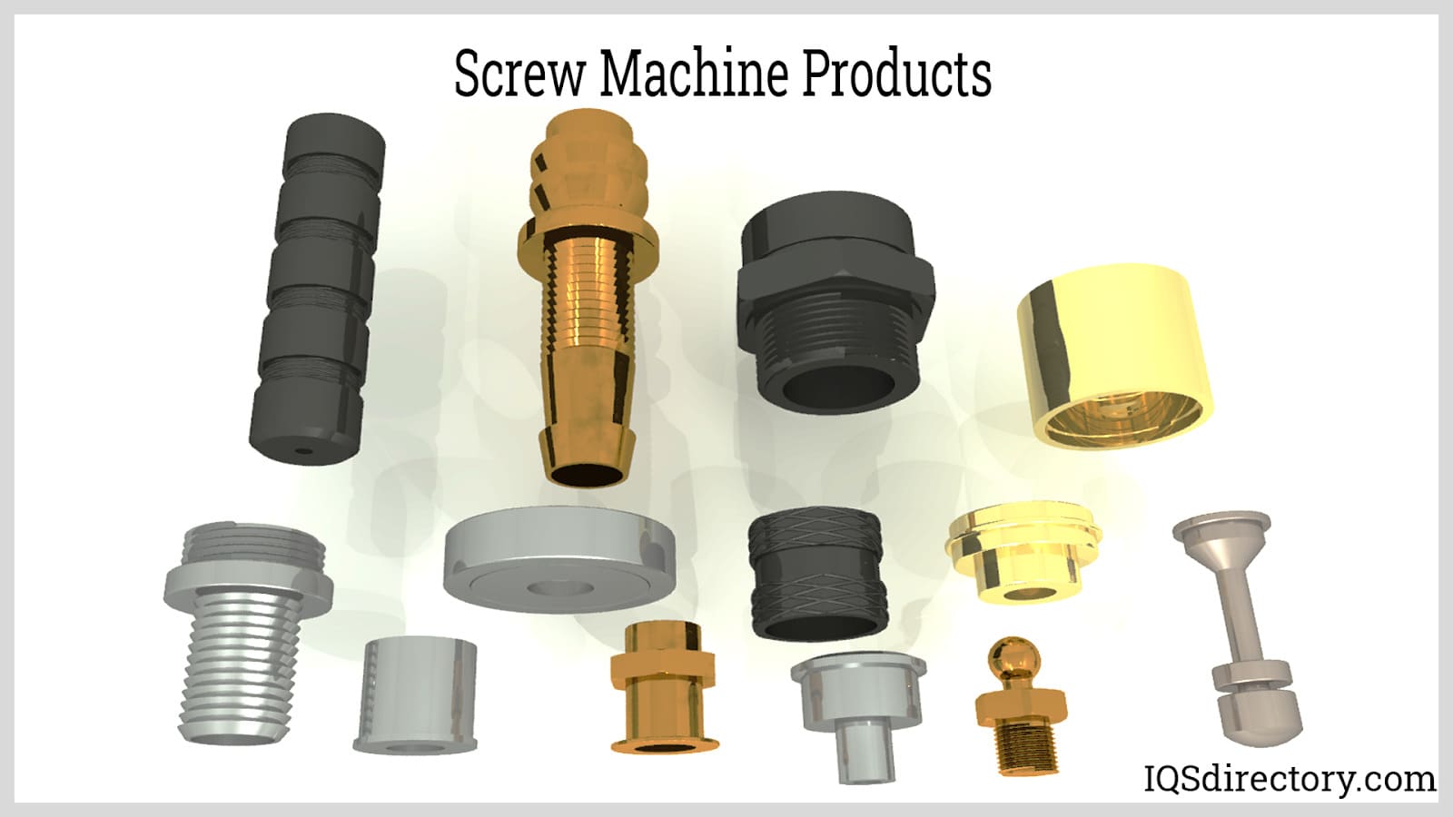
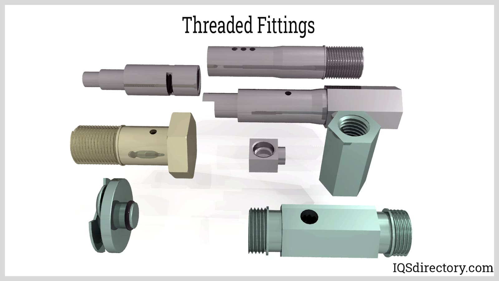
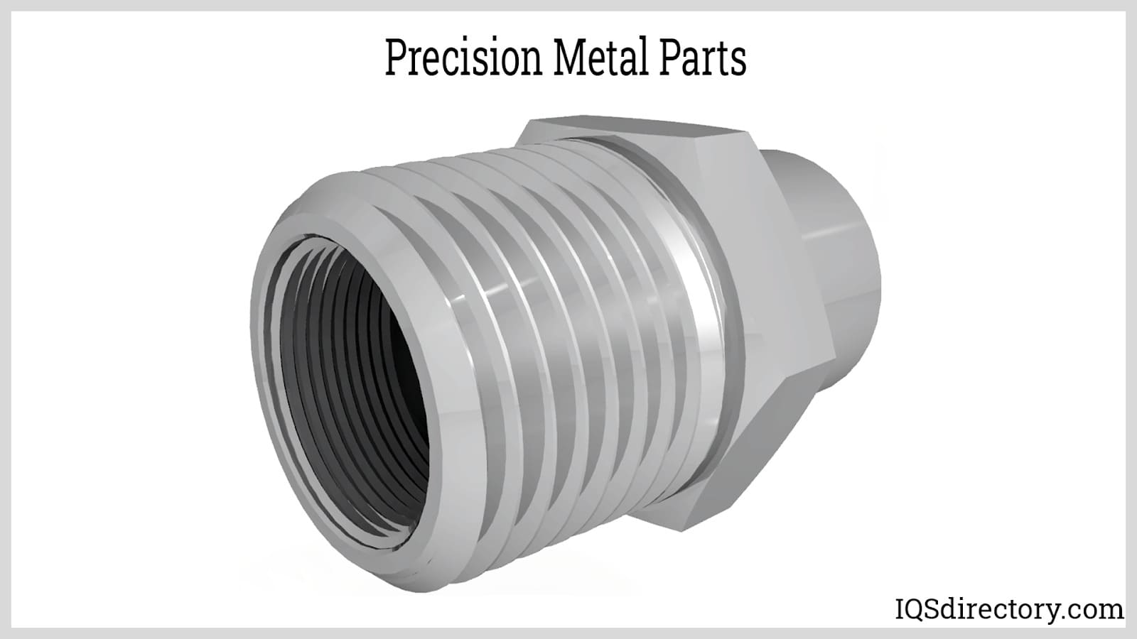
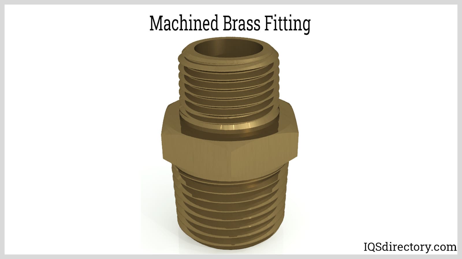
Screw machine products include threaded machine items such as bolts, nuts, and screws. These threaded components can be grouped based on their purpose. Bolts, nuts, and screws serve as structural elements or fasteners. Threaded fasteners may also be integrated into parts, creating threaded fittings.
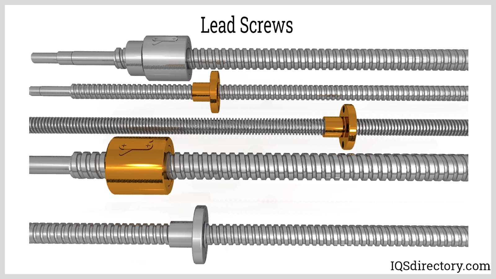
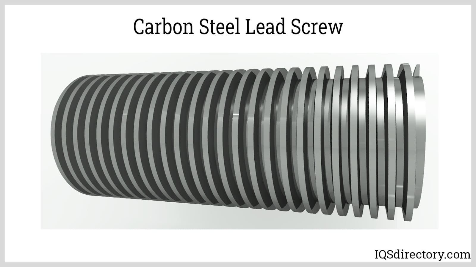
Threaded fasteners are utilized to establish non-permanent connections, allowing for components to be mechanically loosened or disassembled. On the other hand, power screws and lead screws function as mechanical devices or drives, serving as mechanisms to regulate movement and transmit force to other machine parts, thus playing an essential role in mechanical systems.
Screw threads can be classified according to their shapes.
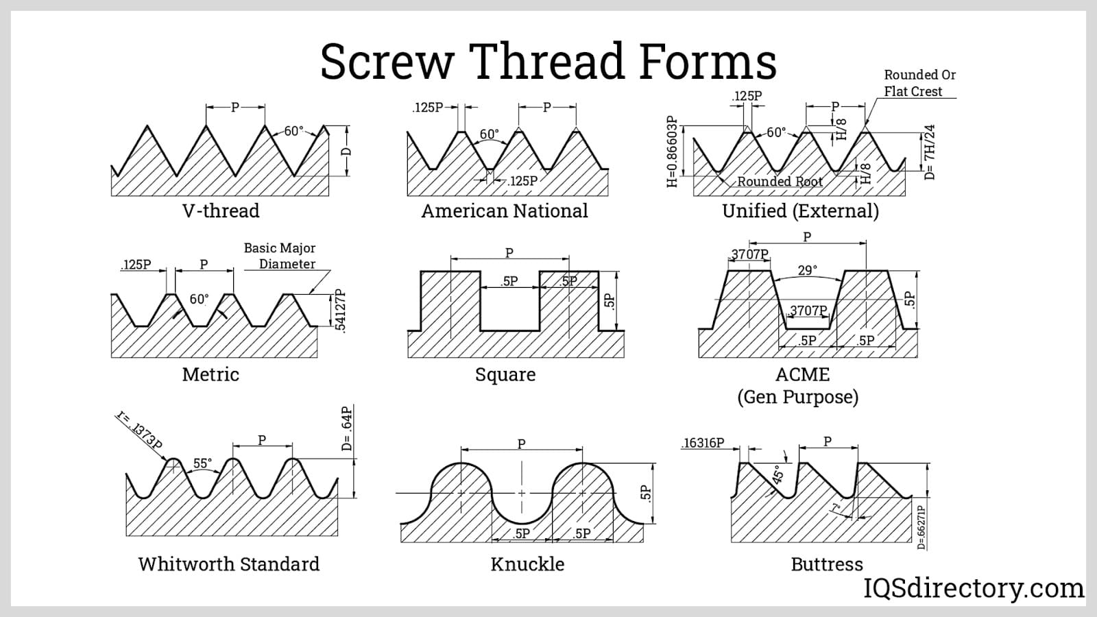

Thread generation processes are fundamental to manufacturing, machine shops, and the production of precision fasteners, screws, and bolts. Understanding threading processes is critical for industries that rely on high-strength, accurately dimensioned threaded components. Thread production is typically classified into three main categories—subtractive, deformative (also called deformation), and additive—each distinguished by how threads are created or formed on metal, plastic, or composite workpieces. These various techniques form the backbone of industrial fastener manufacturing, and each process has unique advantages based on application, thread profile, and product requirements.
Subtractive processes, often referred to as cutting processes in the context of precision machining, are among the most widely used methods. Machinists, toolmakers, and fabrication engineers carefully select these processes based on thread type (internal vs. external), required material strength, thread finish, and production volume. Below is a comprehensive summary of common thread generation methods:
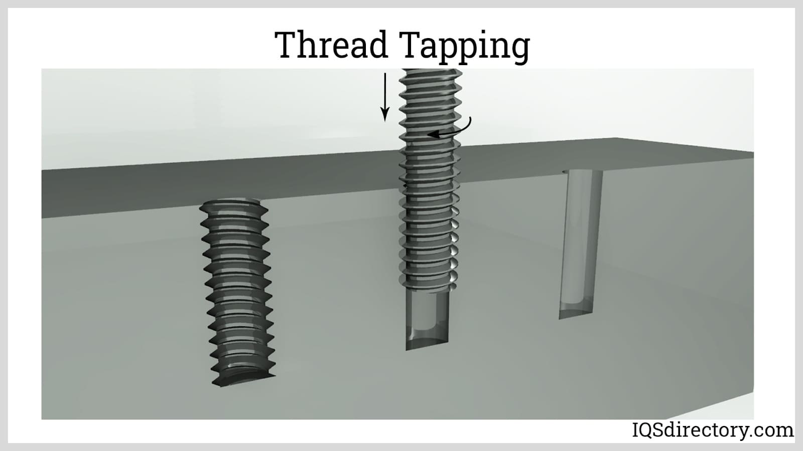
Tapping: Tapping is a thread machining process for producing internal threads, commonly found in nuts and tapped holes. This is achieved using a tap, a cylindrical or conical cutting tool typically made from high-speed steel or carbide. The tap has multiple cutting edges that mirror the external thread form. During thread tapping, the tap is rotated and progressively advanced axially into the pre-drilled hole or bore of the metal stock, cutting the internal thread as it goes. This method is frequently used for thread manufacturing in mass production environments, especially for machined parts requiring high accuracy.
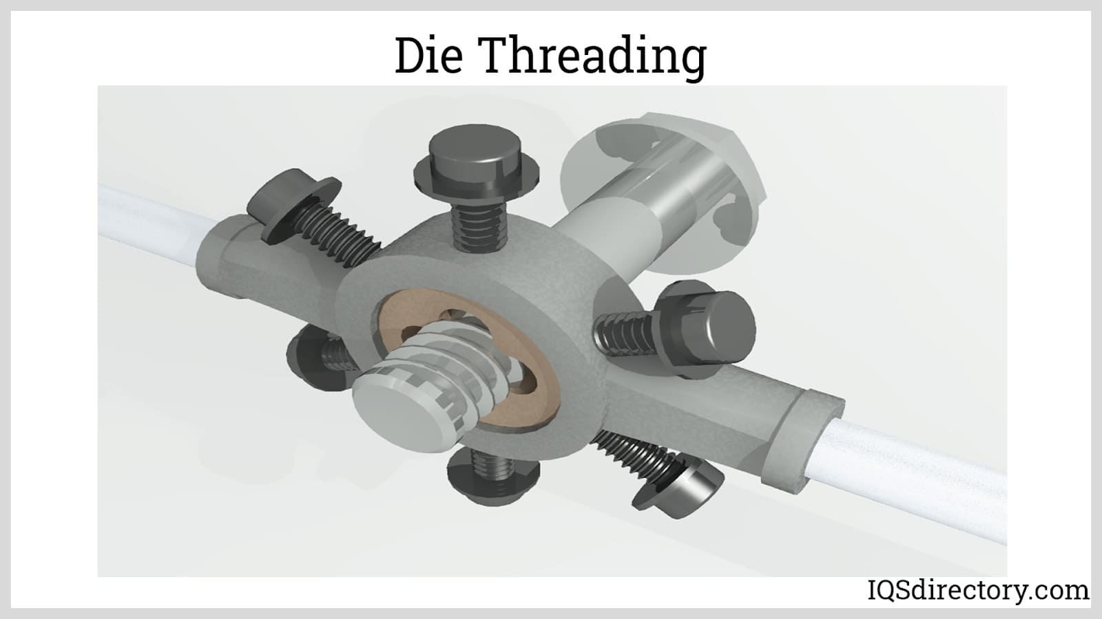
Die Threading: This process is used to produce external screw threads, such as those on bolts, studs, and threaded rods. Its method of applying force and cutting action is similar to tapping, but a die is used to cut external threads onto the metal stock, with multiple cutting points forming the helical thread pattern. Dies are available in solid, self-opening, and adjustable varieties to suit different production requirements. Thread dies provide reliable results for low- to medium-volume production and are ideal for repairs or creating custom threads outside of automated machinery.
Single-point Cutting: Single-point cutting is performed on a lathe or CNC turning center, where the workpiece is securely held and rotated. The cutting tool, precisely mounted on the carriage and fed linearly by a lead screw, traces the helical path to form the thread. This process is suitable for both internal and external threads and is well-suited for creating custom, variable-pitch threads or unique profiles. While single-point threading is slower than tapping or die-threading, its flexibility and ability to cut large or specialized threads make it valuable for prototyping and low-volume, precision applications.

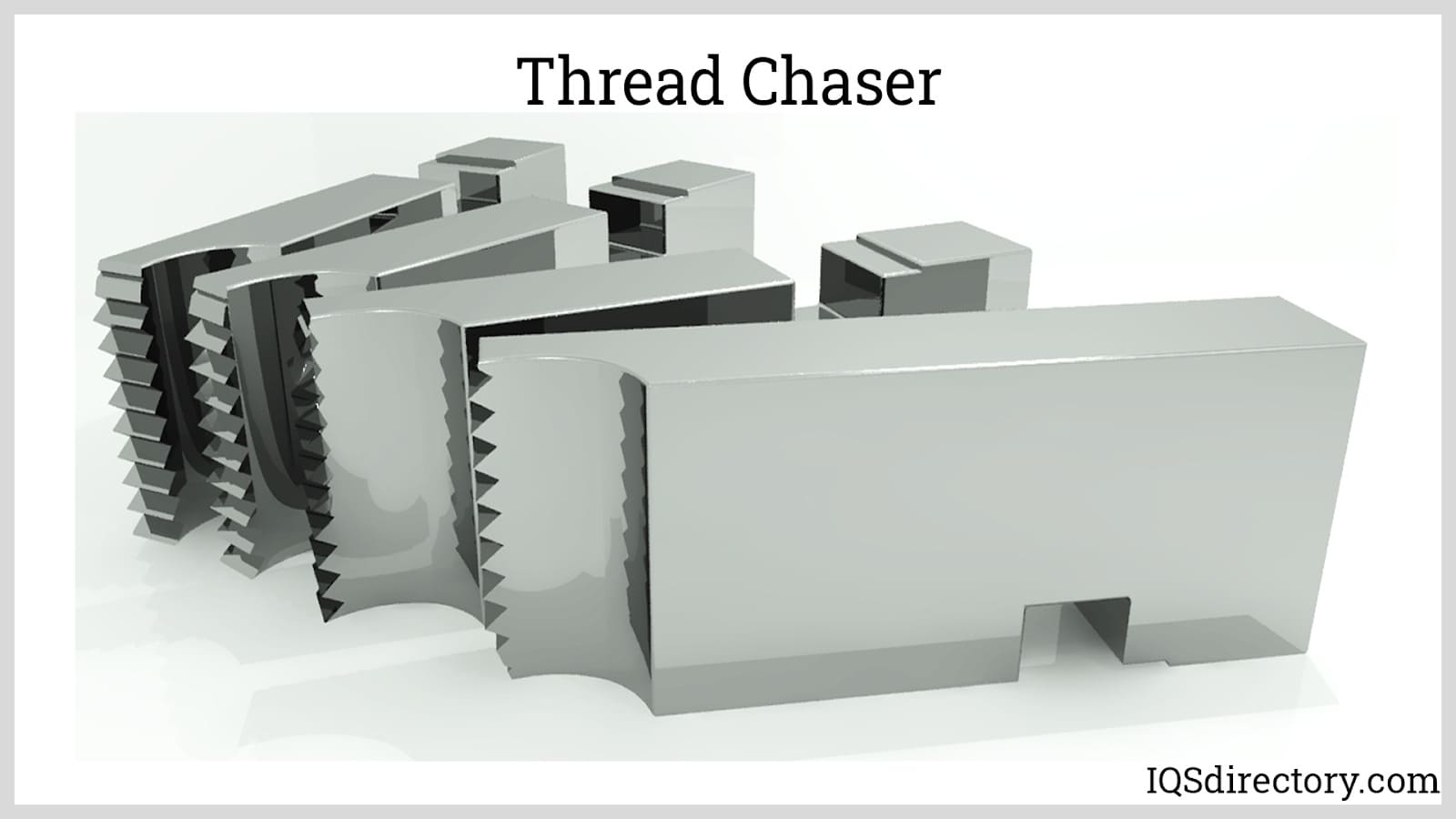
Chasing: This process uses a tool called a thread chaser, which is an assembly of several single-point cutting tools arranged in succession. The thread chaser is typically mounted on the lathe’s carriage, gradually indexed to cut the thread accurately along the workpiece length. Thread chasing is commonly used for large-diameter threads and for restoring worn or damaged threads where precision is critical.
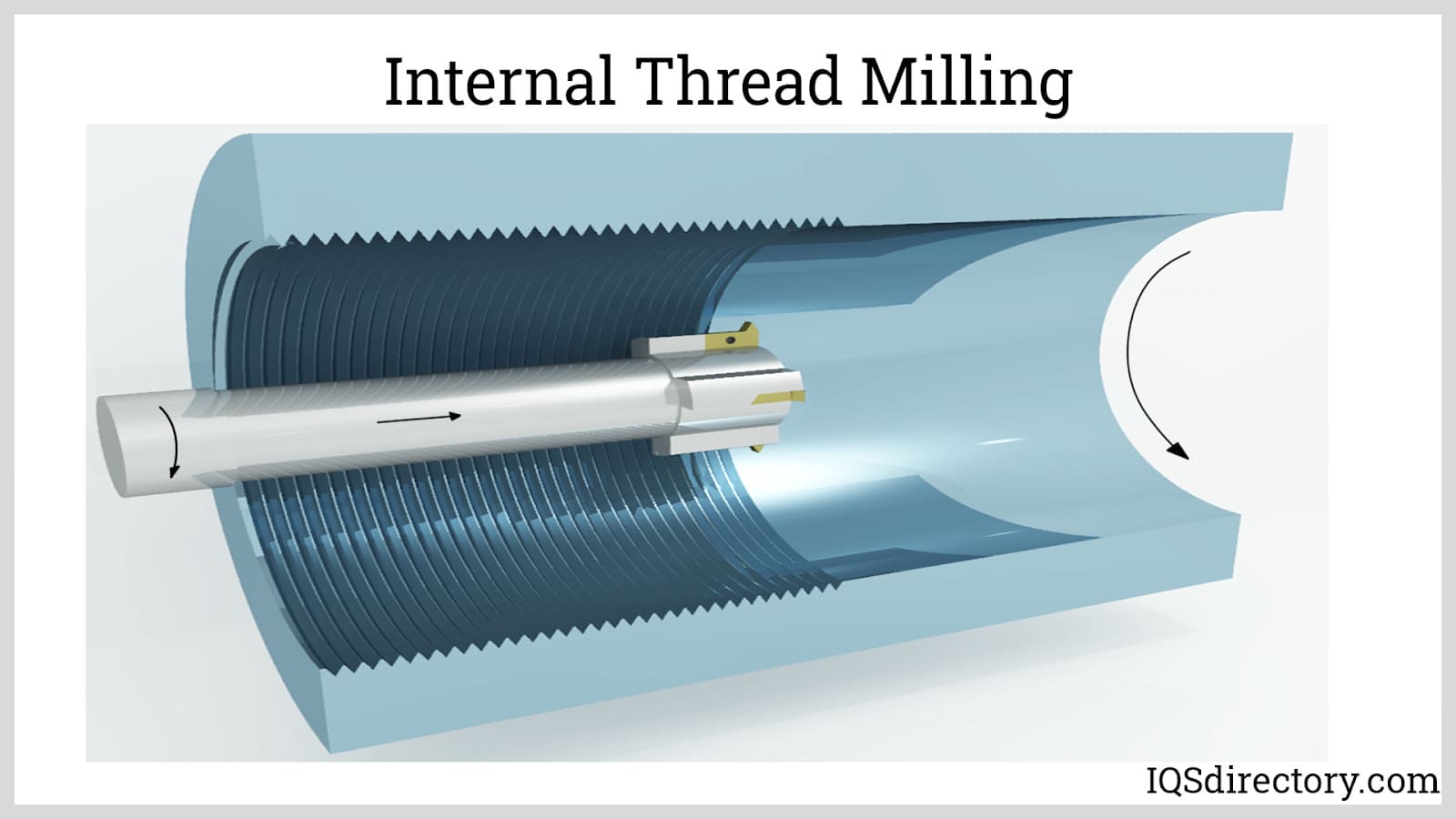
Milling: In thread milling, single or multiple rotary cutting tools are used to machine threads into a workpiece. Unlike tapping or die-threading, thread milling involves the rotation of both the cutting tool and the workpiece along their respective axes, allowing for the creation of both internal and external threads, including tapered and multi-start forms. Thread milling provides exceptional flexibility and is preferred in CNC production for quick changeover, high accuracy, and the ability to run on difficult-to-machine materials such as stainless steel or high-strength alloys.
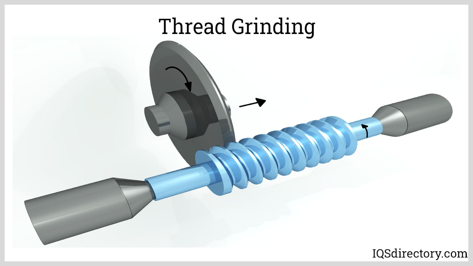
Grinding: Instead of traditional cutting, thread grinding employs abrasive wheels or discs to remove material and achieve a fine surface finish and precise thread dimensions. This process is often used in conjunction with other threading methods and is commonly reserved for hard materials, finishing, or high-precision threaded components such as lead screws, ballscrews, and high-tolerance fasteners. Thread grinding is essential in the manufacturing of aerospace, medical, and instrumentation threads, where tight dimensional tolerances and smooth surface finishes are mandatory.
Deformation (deformative) processes generate threads by displacing and reshaping the metal workpiece without any removal of material. Common deformation threading processes include rolling and casting:
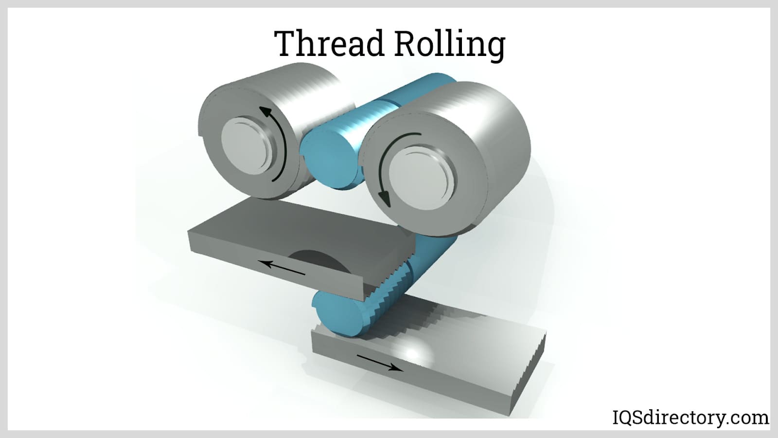
Rolling: Thread rolling is an external threading process that plastically deforms the workpiece by passing it through precision-ground roller dies. These dies have the inverse of the desired thread form and, through pressure and friction, reshape the surface to form threads with improved surface finish and increased strength due to work hardening. Thread rolling is widely used in automotive, construction, and high-volume fastener manufacturing for its efficiency, accuracy, and the enhanced fatigue resistance it imparts to threads. The process is considerably faster than thread cutting and produces no waste material.
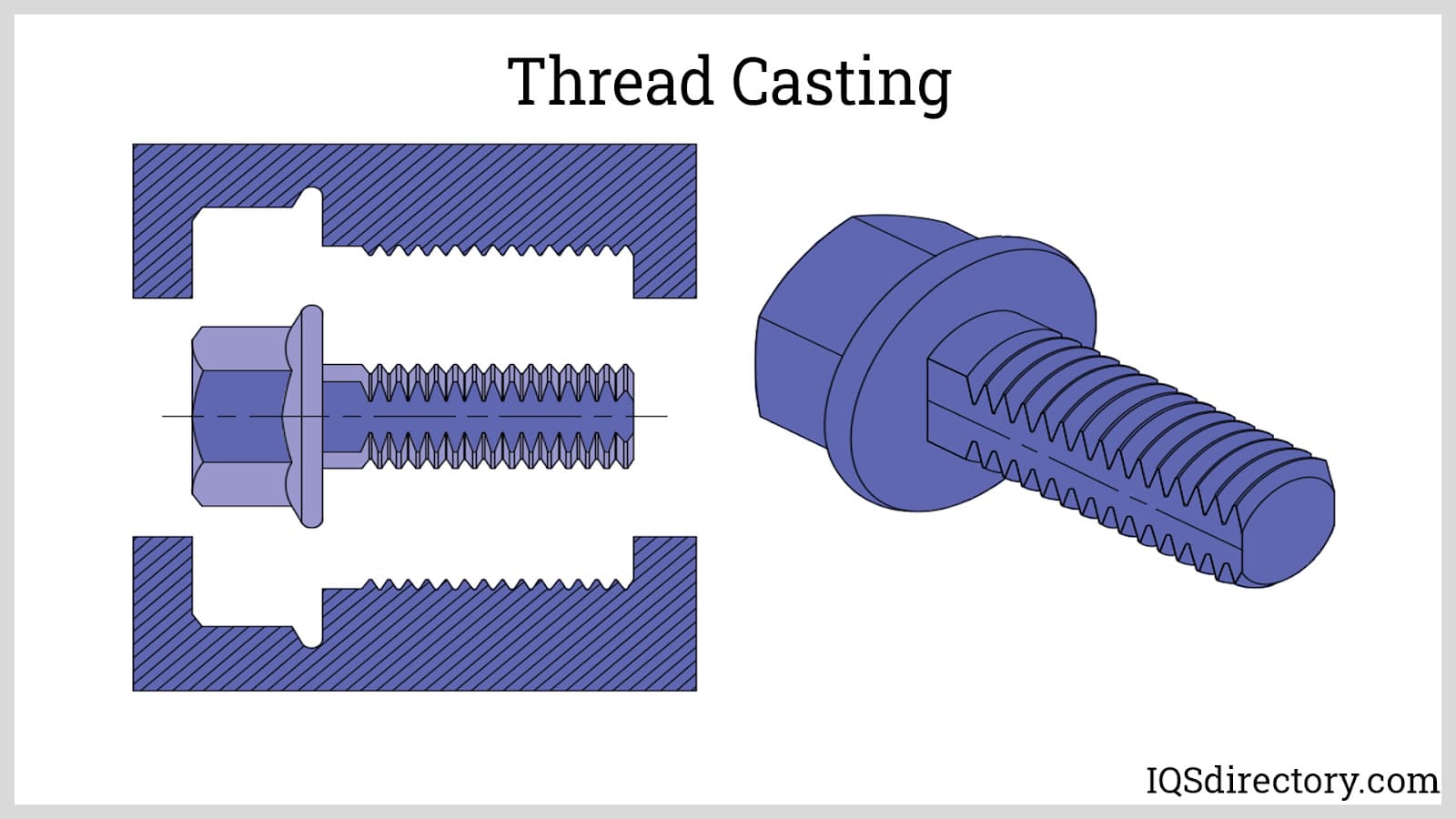
Casting: Thread casting involves pouring or injecting molten metal into a precision die or mold that contains the negative shape of the desired threaded part. While casting is efficient for producing net-shape parts in high volume, it generally requires secondary machining—such as tapping or thread chasing—to achieve accurate threads, particularly for small or fine thread profiles. Among the most common uses of casting in thread manufacturing are for large fittings or coarse threads found in pipe fittings and valves.
Finally, additive manufacturing processes, also referred to as 3D printing, are innovative methods for thread production by precisely depositing material layer by layer. These processes are increasingly applied for prototyping and for manufacturing both plastic and metal parts, especially when complex or custom thread geometries are needed. Currently, additive threading is often combined with secondary finishing operations—such as grinding or lapping—to meet industry tolerances.
Key additive threading techniques include stereolithography, selective laser sintering (SLS), and fused filament fabrication (FFF):
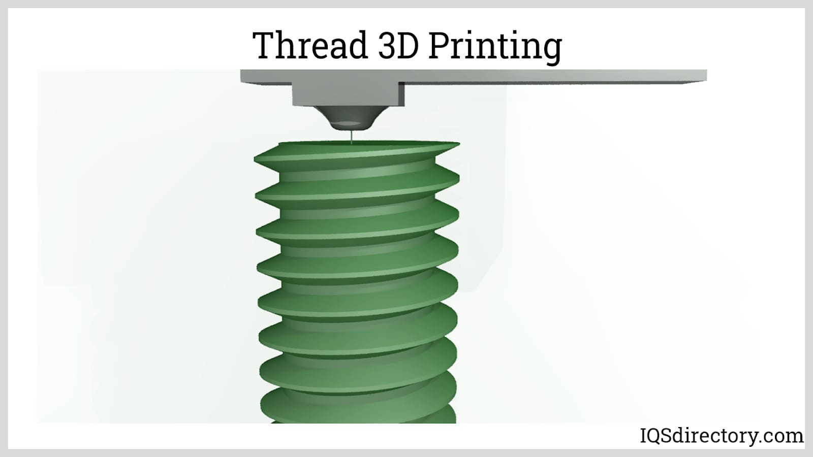
How to Select a Threading Method: Choosing the optimal thread generation process depends on several factors, including material type (such as carbon steel, alloy, aluminum, brass, or plastic), required thread geometry (standard, metric, acme, or custom thread profiles), production volume, cost considerations, and the mechanical properties required of the finished thread. For example, thread rolling is preferred for mass production of high-strength bolts, while thread grinding is chosen for aerospace or medical applications where extreme accuracy and surface finish are critical. CNC threading, incorporating both single-point and thread milling techniques, brings flexibility, efficiency, and repeatability to modern manufacturing environments.
For engineers, purchasing agents, or machinists seeking to specify or source threaded components, understanding the advantages of each technique ensures optimal performance, longevity, and cost-effectiveness. Partnering with a trusted threaded fastener manufacturer or precision thread supplier is crucial for applications with tight tolerances, custom designs, or specialized requirements.
Utilizing a thread rolled screw machine product presents a unique set of advantages and disadvantages within precision manufacturing. Thread rolling, a dominant process in the fastener manufacturing industry, offers superior mechanical properties, enhanced fatigue resistance, and excellent surface integrity. The primary benefit of thread rolling is its ability to produce stronger, more durable threads with high dimensional consistency and accuracy. However, since this process relies on plastic deformation of the material, it is generally restricted to ductile, soft metals and often involves higher initial tooling and setup costs compared to thread cutting methods such as thread grinding or thread tapping.
Below are the core benefits of rolled threads, screws, and bolts in modern manufacturing:
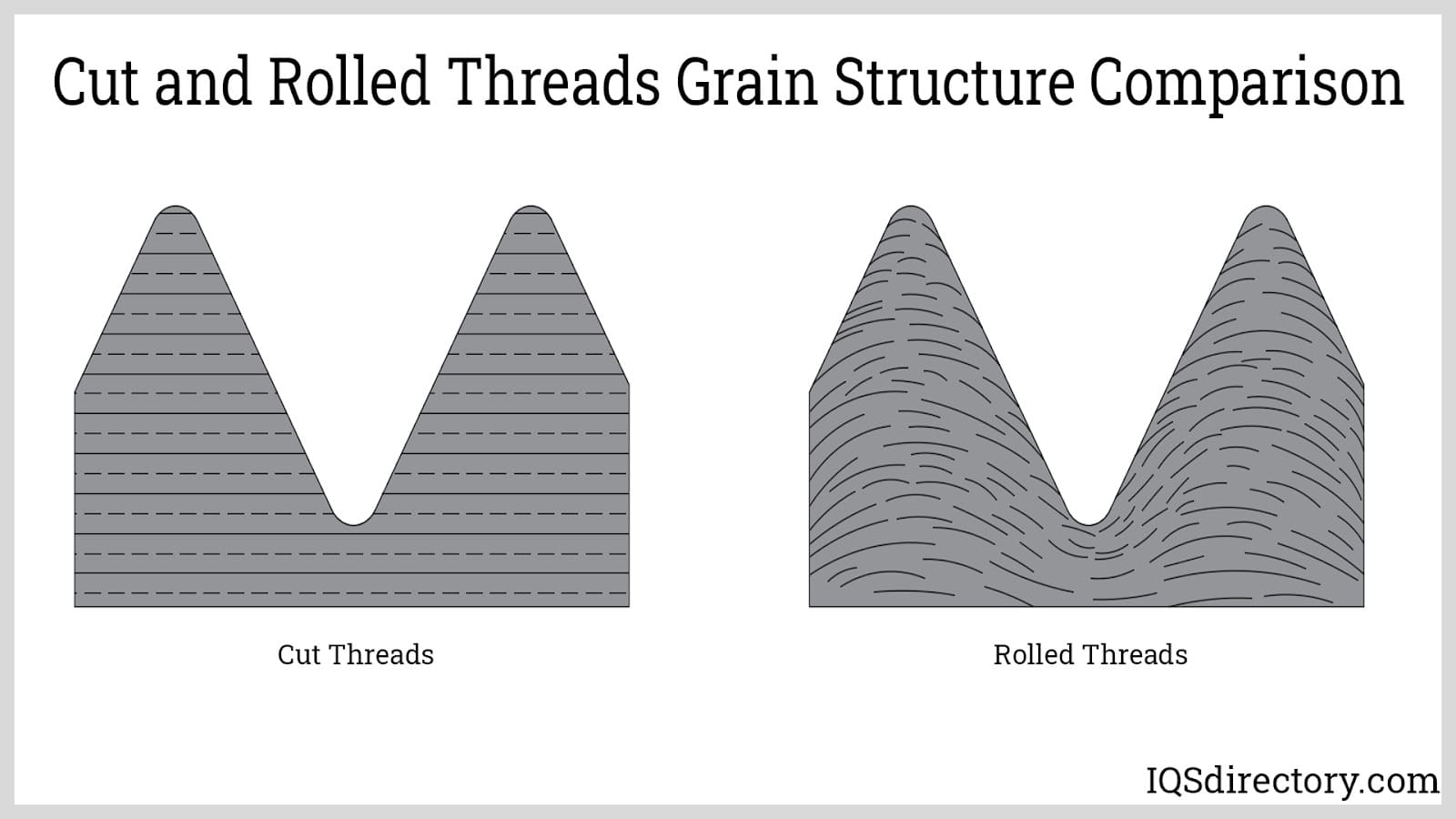
High thread strength and load-bearing capability: Thread rolling is usually conducted at relatively low temperatures, making it a cold forming process. Cold working significantly increases material strength and produces threads with dense grain flow—enhancing tensile strength and fatigue life. Rolled threads are 10 to 20 percent stronger than cut or ground threads, making them the preferred choice for applications requiring superior thread integrity, such as in aerospace, automotive, and critical structural assemblies.
Precision threading and repeatability: The use of mirror-image dies in thread rolling ensures tight tolerances and consistent thread geometry over large production runs. Since no material is removed, the thread profile remains stable and uniform. This makes thread rolling ideal for the mass production of fasteners, lead screws, threaded rods, and precision components where high accuracy is required from batch to batch.
Cost efficiency via minimized material waste: Because thread rolling is a non-cutting, chipless forming process, the original metal stock is fully utilized, eliminating the need to handle removed metal chips. This results in better material yield and decreased energy and recycling costs, making thread rolling an environmentally friendly, sustainable manufacturing process.
Despite substantial benefits, manufacturers should consider the limitations of thread rolling as these can impact product cost and process selection. Most downsides impact the manufacturing process more than the end-user, but ultimately contribute to the final pricing of rolled thread products.
Not suitable for high-hardness metals: Thread rolling is generally applied to malleable metals including low-carbon steel, alloy steel, aluminum, copper, and certain stainless steel grades. Processing materials harder than 40 Rockwell C dramatically reduces tool life and process efficiency. For hardened or heat-treated steels, thread grinding or other specialized methods are recommended for optimal results.
Choosing between thread rolling and cutting depends on application-specific requirements such as material hardness, thread strength, production volume, and desired surface finish. Manufacturers targeting high-strength fasteners, precision threaded connectors, or custom screw machine products should evaluate both the technical and economic aspects of thread rolling in light of their specific needs.
If you are comparing thread rolling versus thread cutting methods for your application, consider engaging with an experienced contract manufacturer or fastener supplier. Request thread samples, tolerance documentation, and load-bearing data to ensure the selected threading process aligns with your quality and budget expectations. For unique or specialty projects, prototype fabrication and application testing may be recommended to confirm optimal thread performance. Learn more about the differences between thread rolling and cutting here.
Thread rolling deforms metal between dies to create threads, enhancing strength and surface finish. Unlike thread cutting, it is a non-subtractive process, removing no material and producing denser, stronger threads.
Thread rolling is best for ductile, malleable metals such as low-carbon steel, alloy steel, aluminum, copper, and select stainless steel grades. It is not suitable for metals harder than 40 Rockwell C.
Thread rolled fasteners offer higher thread strength, superior surface finish, tight dimensional tolerances, reduced friction, faster production rates, and minimal material waste compared to cut threads.
Thread rolling is ideal for mass production of high-strength fasteners, bolts, and screws where strength, accuracy, repeatability, and efficient production are priorities, especially in industries like aerospace and automotive.
Key limitations include unsuitability for hard metals, higher tooling and setup costs, and strict requirements for precise stock diameter, sometimes necessitating pre-turning or centerless grinding.
Thread rolling machines can quickly output large quantities of threaded components with consistent quality, making it a strategic choice for fastener, bolt, and screw manufacturing requiring short lead times.
As with any machining process, several factors must be considered to ensure optimal operating conditions and product quality. Below are some of the key variables that impact thread rolling.
Stock Diameter: The correct stock diameter is almost the same as the pitch diameter of the screw or bolts. Usually, the space or cavity between the threads and below the pitch line is the same as the volume of the thread above the pitch line. Some adjustments for tolerances may be needed to attain the desired crest formation, especially if secondary processes such as coating, or plating are needed to be done.
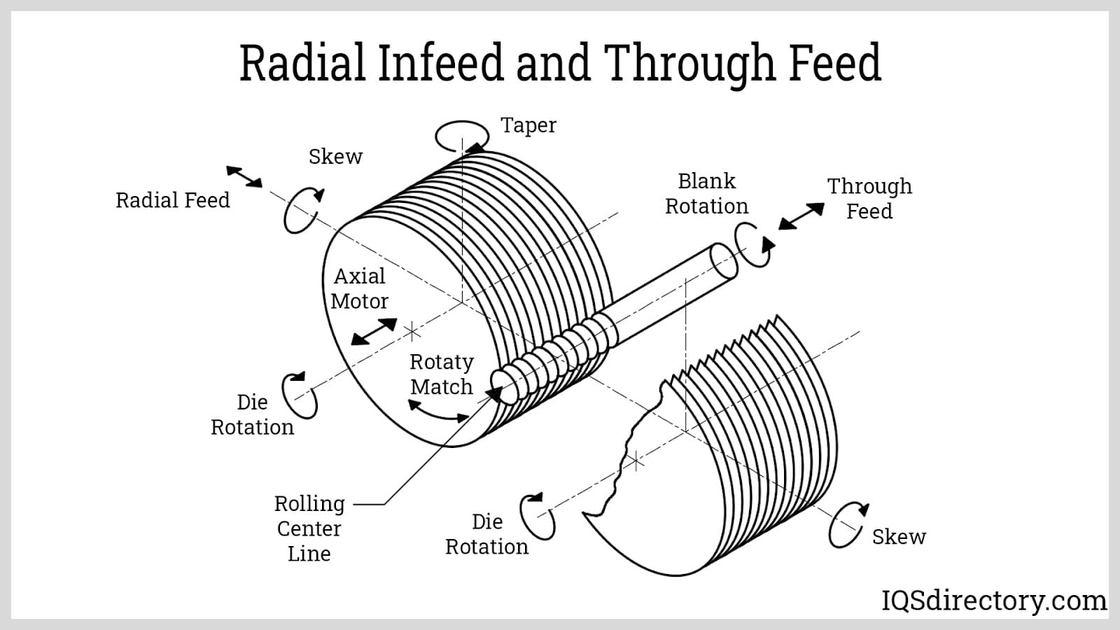
Feeding: There are three basic techniques for feeding the stock into the dies: radial infeed, tangential feed, and through feed. In radial infeed, the dies move radially towards the axis of the stock. For tangential feed, the pitch of the stock approaches the rollers from its side making square, tangential contact. Lastly, through feed involves a cylindrical die that mates against the stock causing it to move axially.
Although the thread rolling process provides higher precision compared to other methods, defects can still occur due to upsets and irregularities in the operation. Common issues include out-of-tolerance stock dimensions, worn or misaligned rollers, and improper stock feeding. The following are the most frequent defects observed in thread rolling.
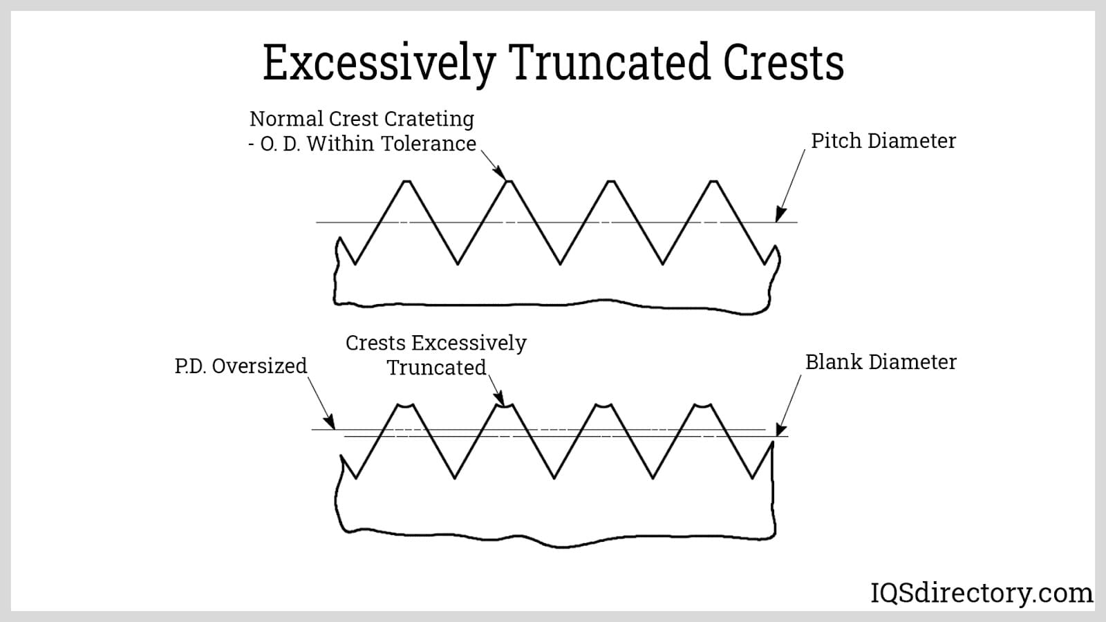
Truncated Thread Crest: This defect is described by a non-fully formed crest or an excessively truncated crest. One reason could be an undersized stock where there is insufficient material to flow and create the crests. This is fixed by gradually increasing the size of the stock. If the pitch diameter is oversized, then the more probable root cause is a loose threading head which is solved by sizing-in. If not, then the defect is possibly caused by too much hardness of the material. Thus, it is then necessary to change into a softer material.
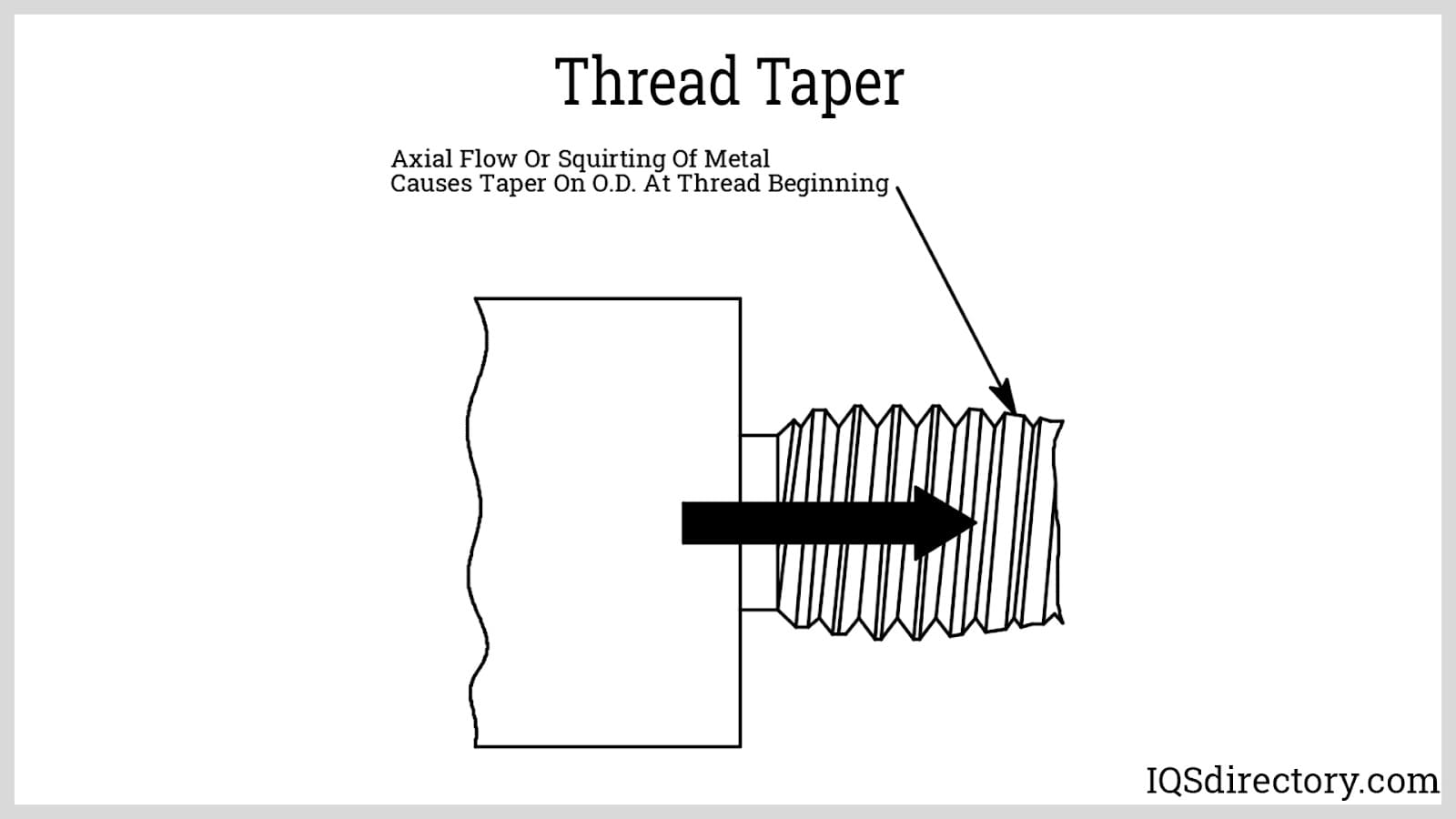
Curved Pitch Line: This is viewed as the tapering of the threads towards the ends of the threaded segments of the bolt or screw. The curvature can be concave or convex. Its root causes are inconsistent stock diameter, misaligned stock relative to the roller, wearing of rollers, or too much deformation of the material causing it to flow towards the end of the stock.
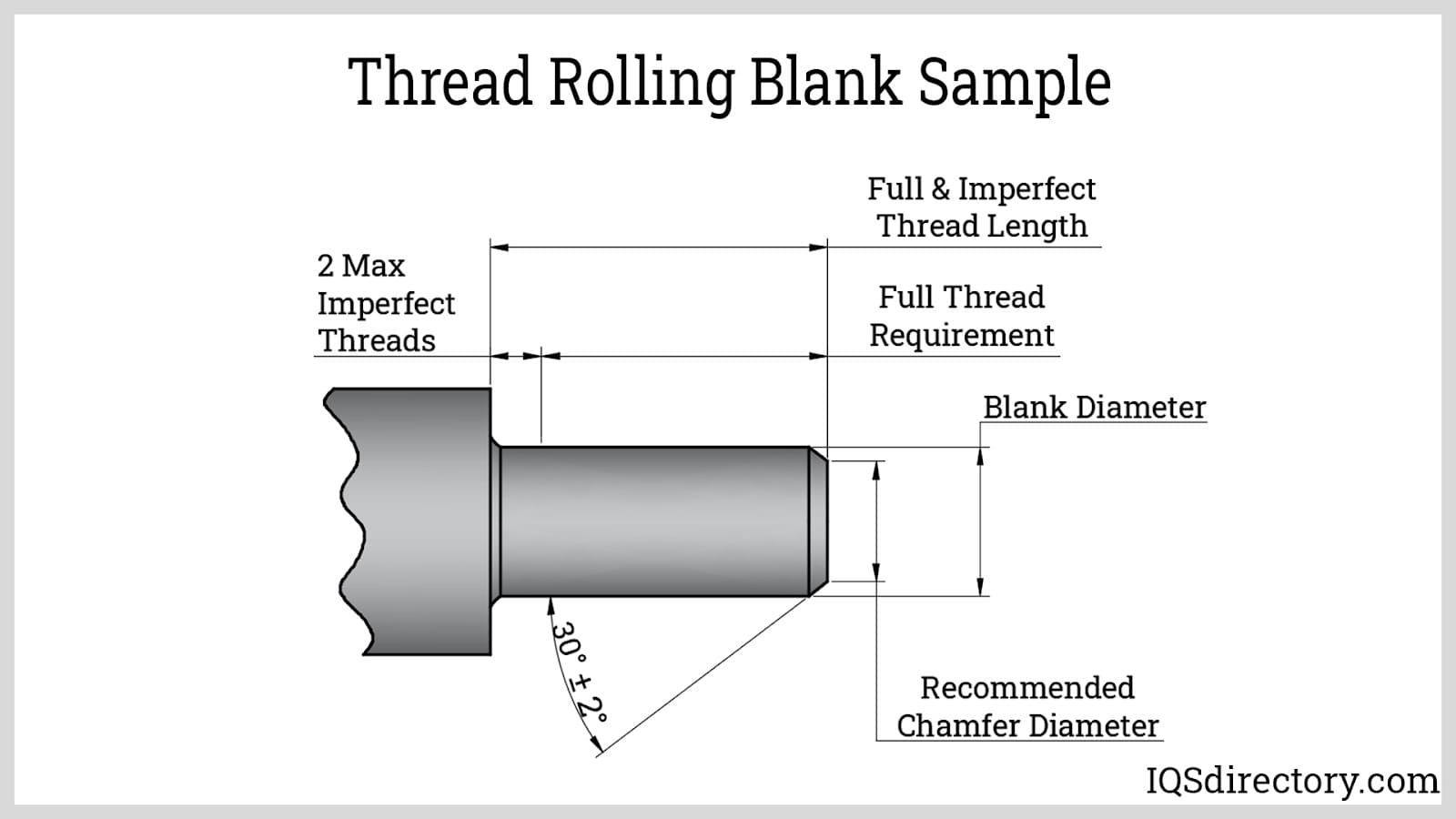
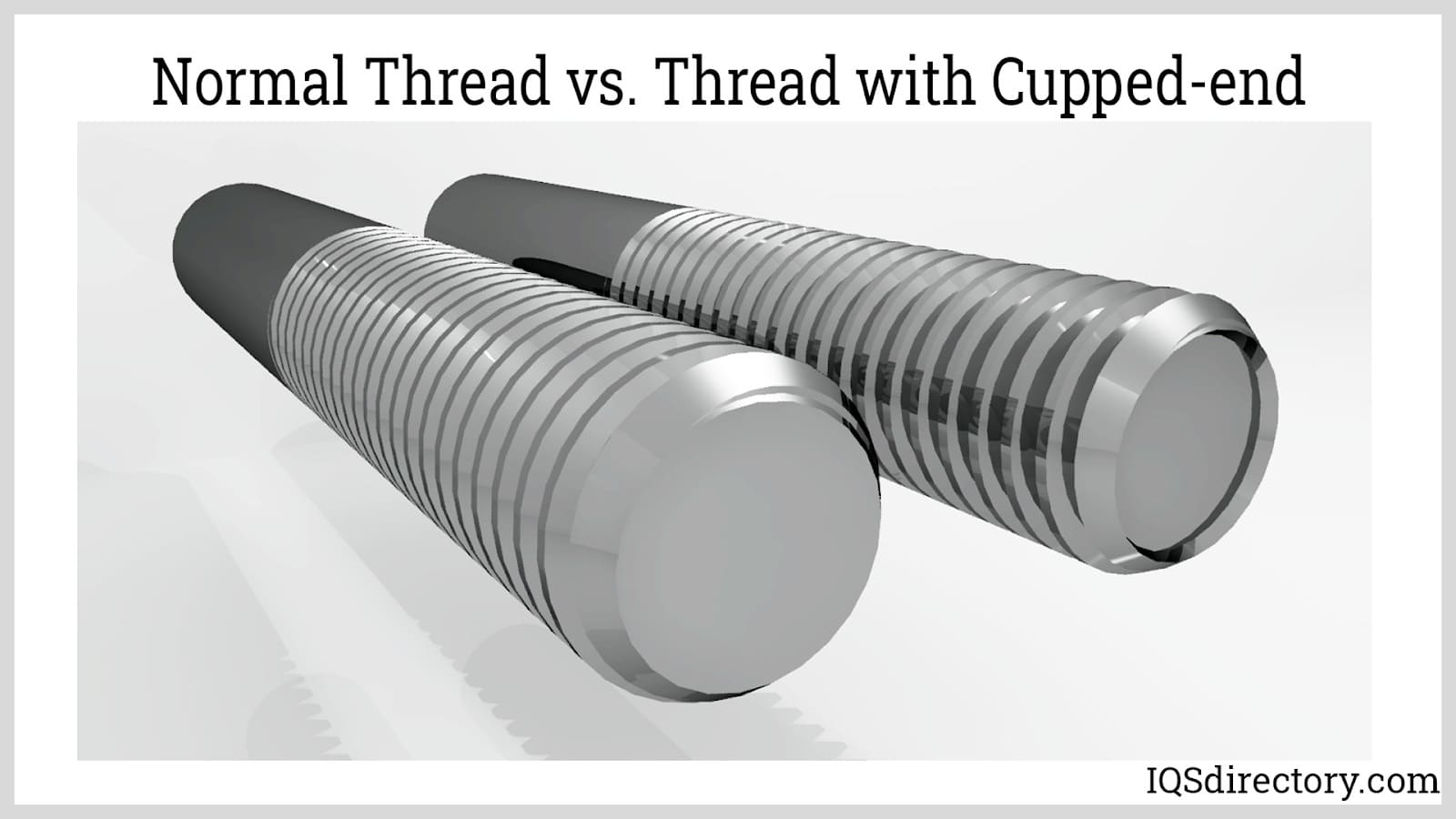
Cupped End: A cupped end appears as a concave-end caused by forcing the metal to flow over an insufficient chamfer. This is more evident on softer metals. The defect is solved by properly chamfering the stock, usually about 30°.
Thread rolling is a straightforward process that begins with cutting a metal bar to length and forging it to create the bolt or screw head. Next, the bar is machined to achieve the correct stock diameter and a chamfer on one end. The prepared stock is then fed into the threading machine, where it passes through dies to shape the thread. After the thread is rolled, the stock undergoes secondary processes such as plating, anodizing, and coating.
This process summary applies to all types of thread rolling. However, thread rolling machines differ based on the type of die used. They can be categorized into flat-die, planetary, or cylindrical-die types.
Flat-die Type: This type of thread rolling machine consists of two rectangular dies where one is stationary while the other is reciprocating. The reciprocating die moves parallel to the stationary die. The surface of the dies contains ridges representing the profile of the thread to be produced. These ridges are inclined at an angle equal to the helix angle of the thread. The distance between the crests of the dies is equal to the minor diameter of the thread.
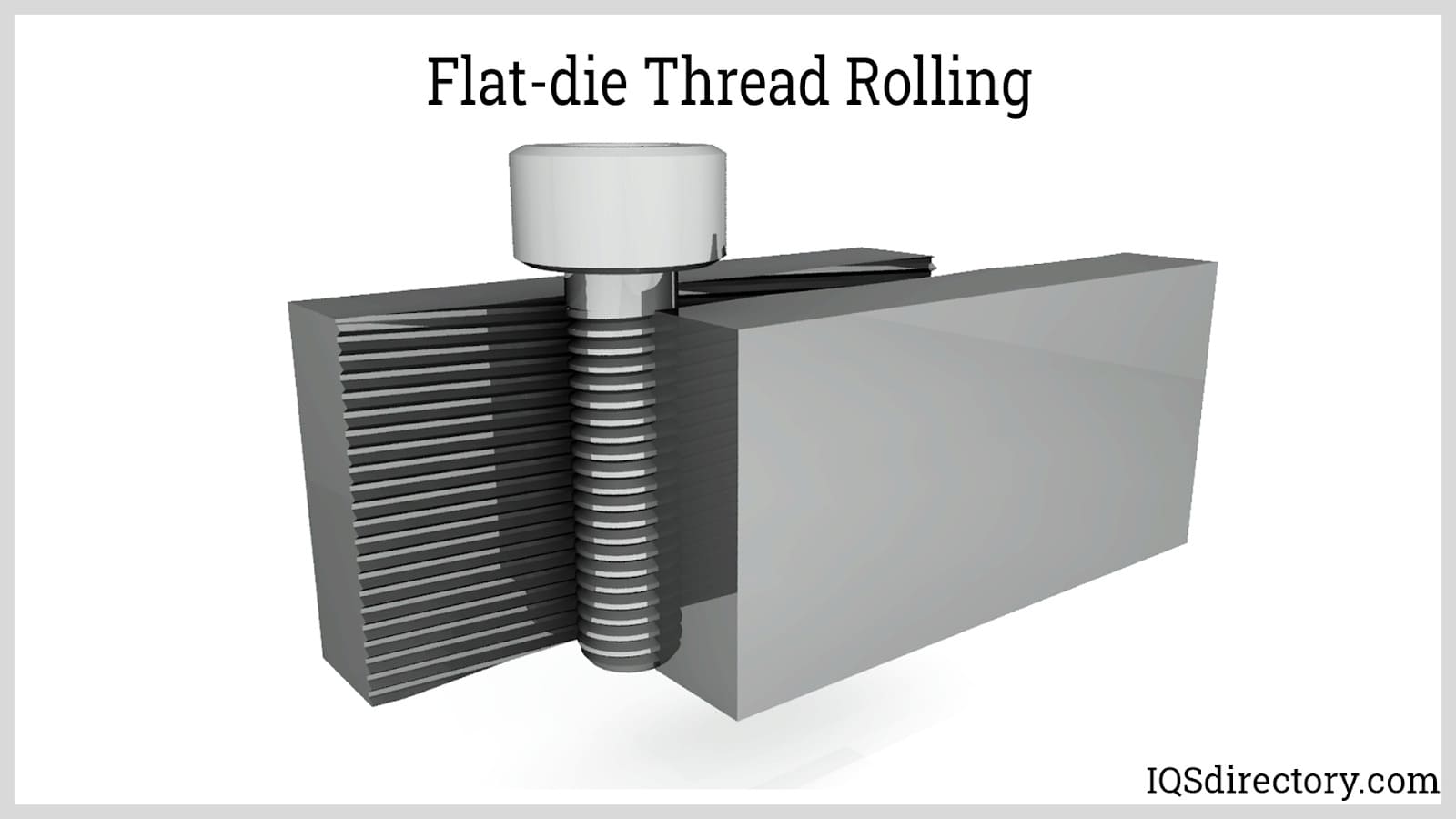
The threads are formed typically in one passage only. The length of the die allows the stock to be rolled around six to eight times. The stock is inserted on one end, either manually or automatically. The dies roll the stock tangentially which carries it up to the opposite end by friction.
Segment or Planetary Type: A planetary type operates by rolling the stock through one stationary and one moving surface. However, this machine uses rotating motion instead of translation. This type involves stationary curved dies and a central rotating die. One or more stationary dies can be matched with a single rotating die. A stationary die rolls one stock at a time.
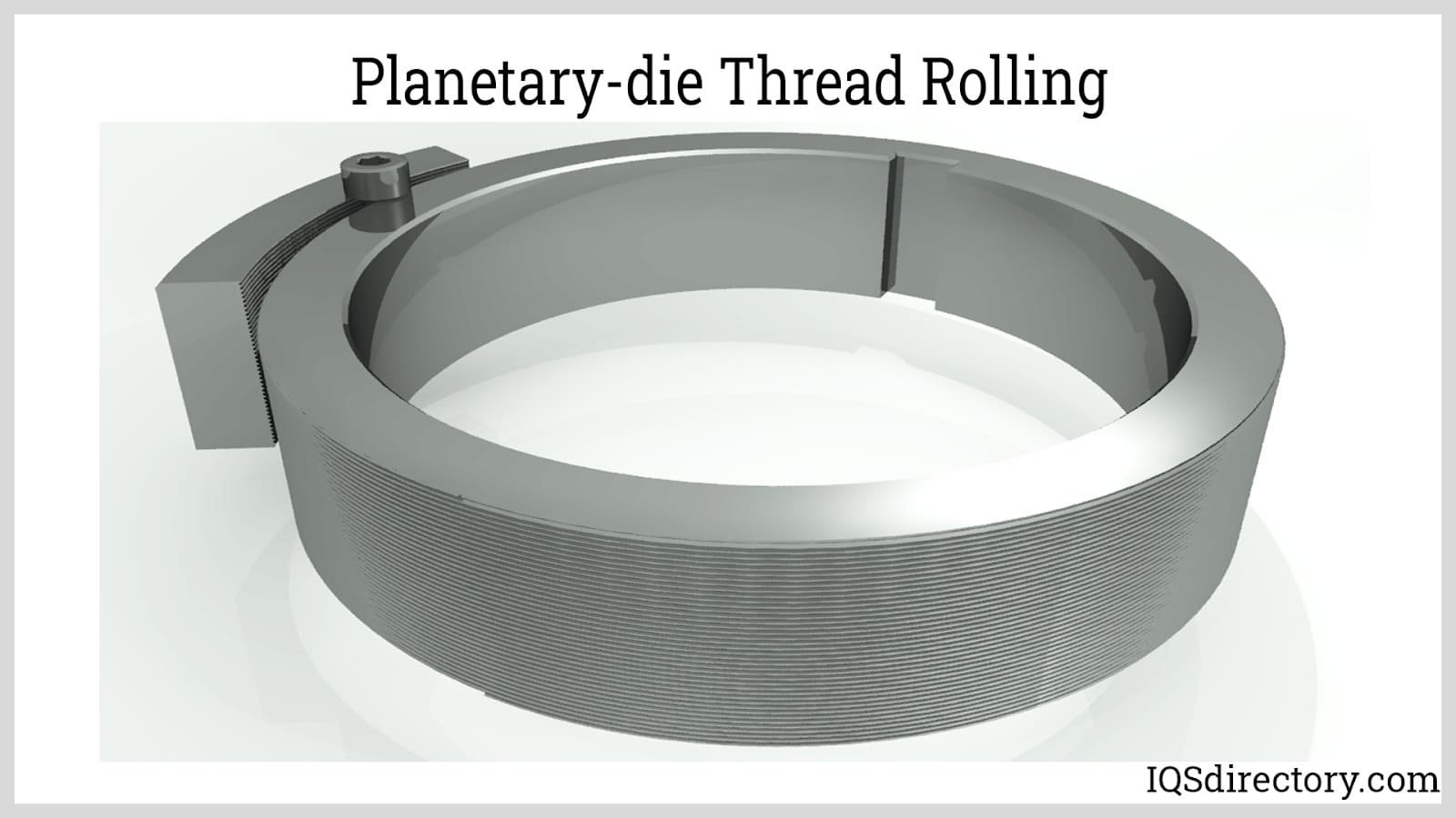
Similar to the flat-die type, the planetary machine has a finite rolling surface that forms the thread through one passage. The stock is inserted on one end of the curved die. The rotating die then rotates a full arc of the curved die revolving the stock until ejected on the opposite end.
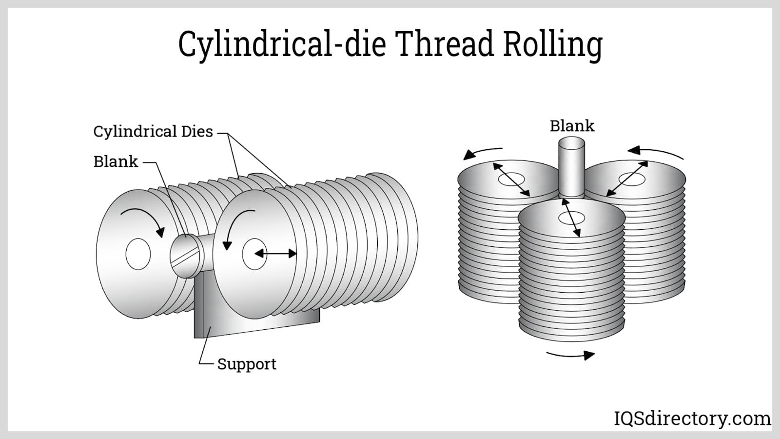
Cylindrical-die Type: Cylindrical dies or rollers are regarded as dies with infinite work surfaces. These machines usually operate through the combination of radial and through feeding. Unlike the flat-die and planetary types, the cylindrical-die type deforms the metal through multiple passes as it rolls. Cylindrical-die type machines can be further divided into two major categories: two-die and three-die machines.

Screw machined parts are complex pieces that are typically cylindrical and threaded and a screw machined product is a family of automatic lathes for small to medium-sized components...
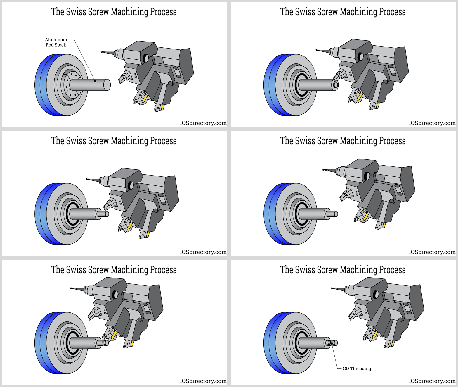
Swiss screw machining is a process for producing high precision parts in high volume using an automatic lathe that is programmed to perform every aspect of the cutting process. The method used for...
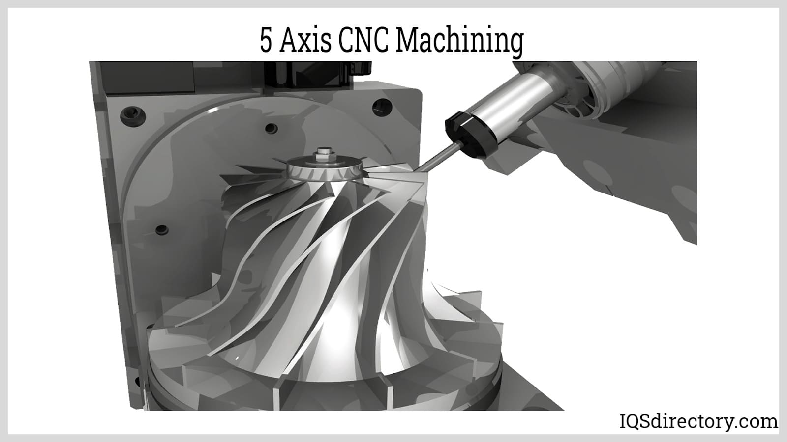
The normal functioning of CNC machines is done along the three Z, X, and Y axes. The five axes machines have two more axes accessible, which are namely A and B. The addition of the two extra axes makes it easy to cut complex and intricate parts...
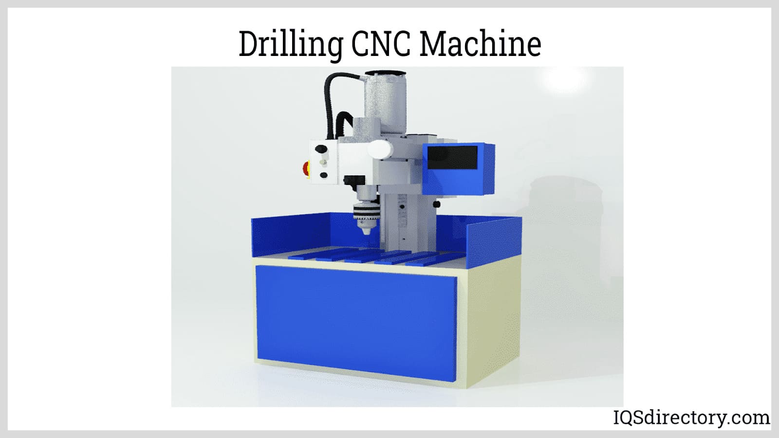
CNC machining is an electromechanical process that manipulates tools around three to five axes, with high precision and accuracy, cutting away excess material to produce parts and components. The initial designs to be machined by CNC machining are created in CAD...
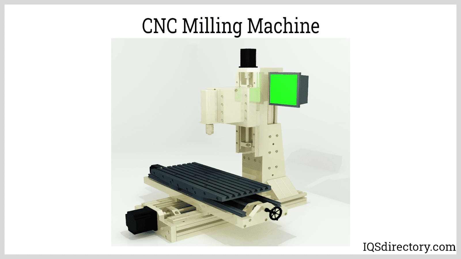
The CNC process was developed in the 1950‘s and took a leap forward in the 1980‘s with the addition of computerization. Unlike other production processes, CNC begins with a rendering by a computer, which creates a two or three dimensional representation of the part to be produced...
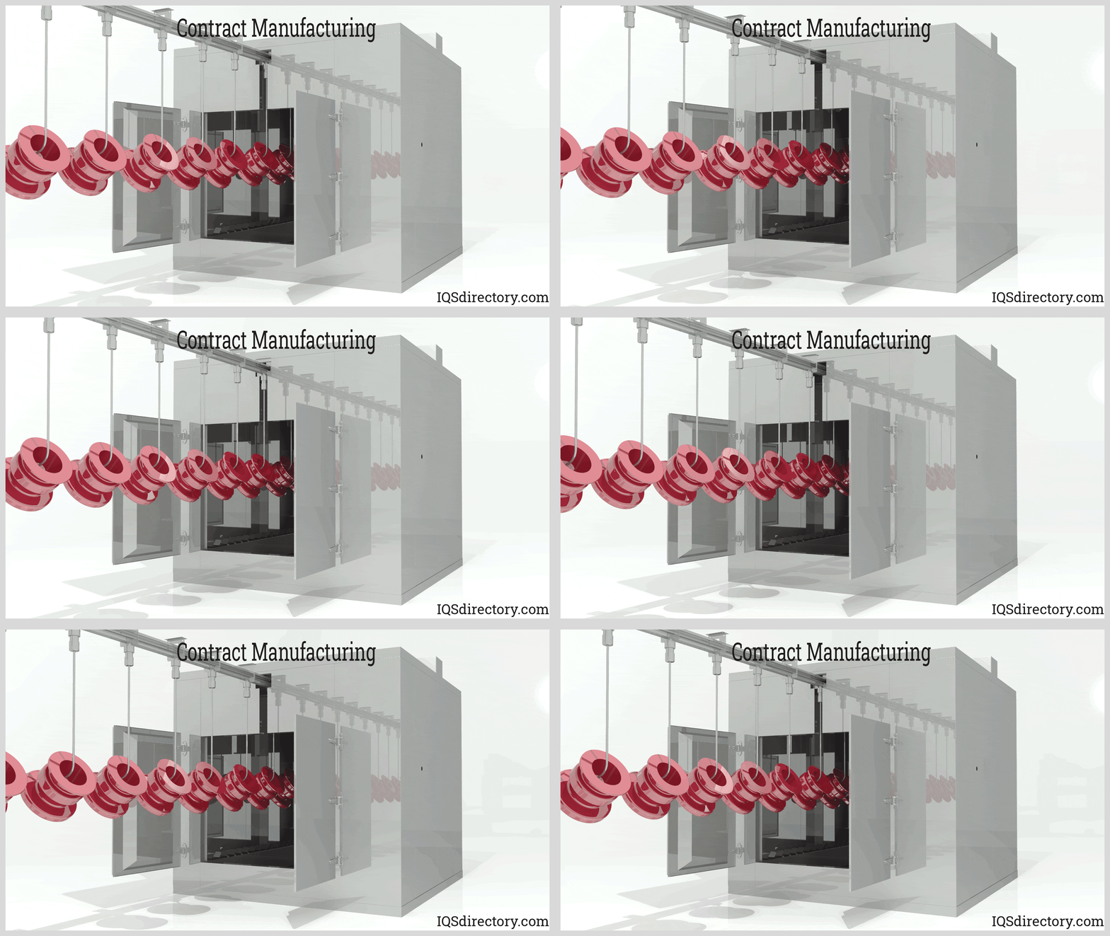
Contract manufacturing is a business model in which a company hires a contract manufacturer to produce its products or components of its products. It is a strategic action widely adopted by companies to save extensive resources and...
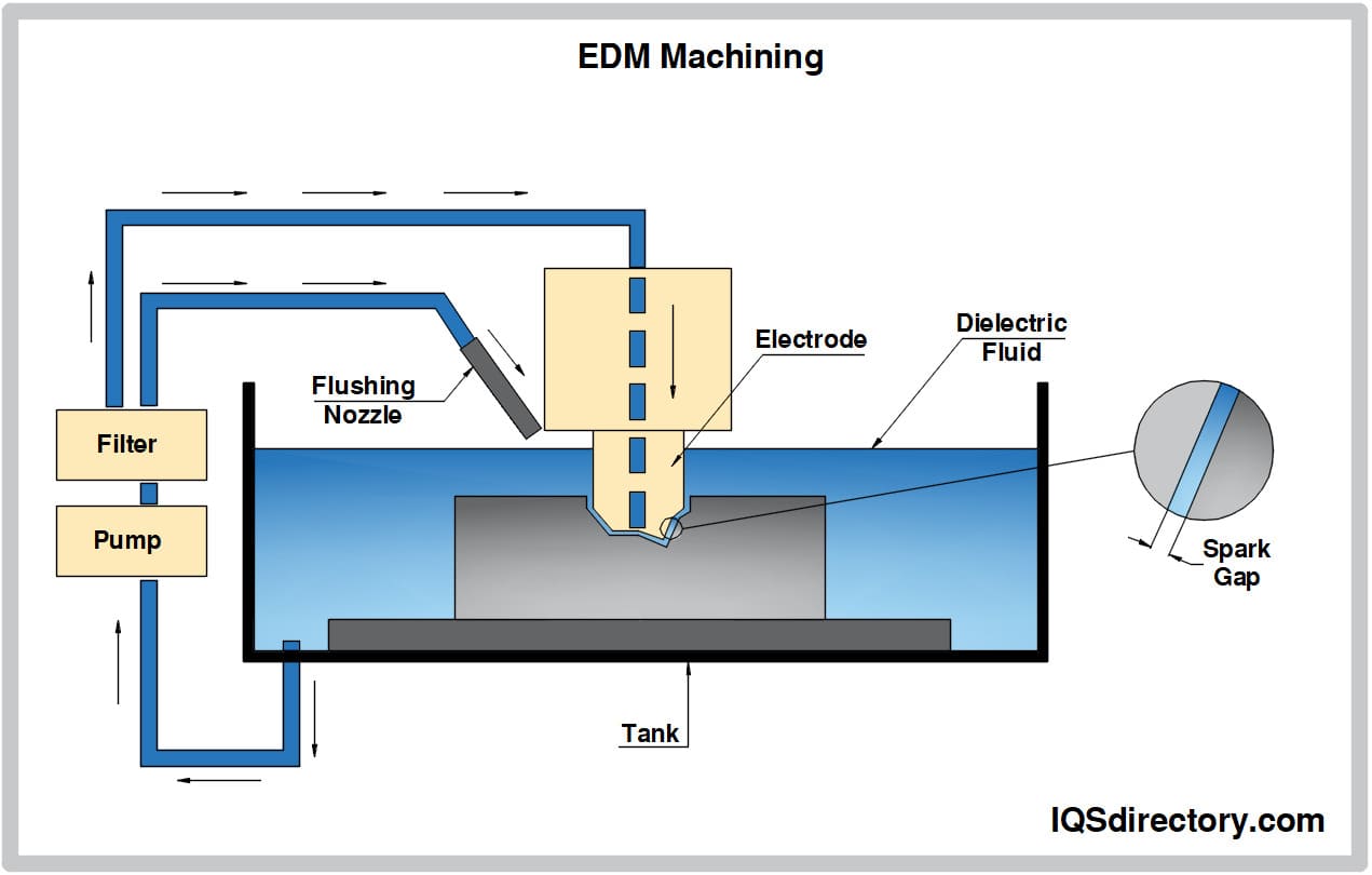
EDM machining is a contemporary machining method based on the removal of material from a part using thermal energy. The material is removed by local melting or vaporizing small areas on the surface of the part being machined...
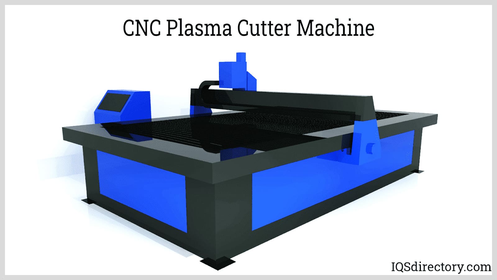
G-code is the name of a plain text language that is used to guide and direct CNC machines. For most modern CNC machines, it isn‘t necessary to know the meaning of G-codes since CAD and CAM software is translated into G or M codes to instruct a CNC machine on how to complete a process...
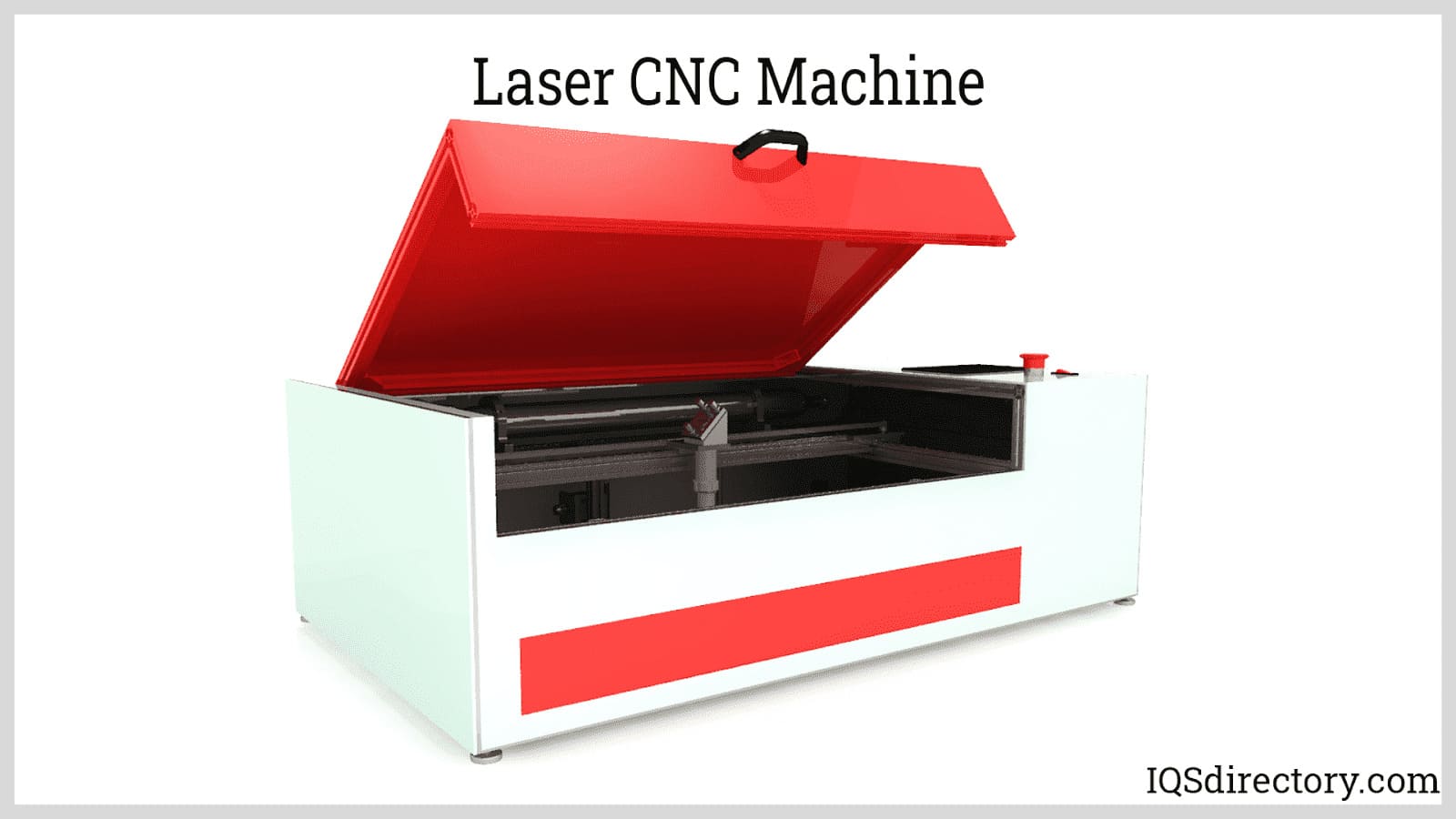
Computer numerical control (CNC) is a fundamental part of modern manufacturing. The majority of machines operate using instructions and guidelines that have been downloaded using a CNC program controller...
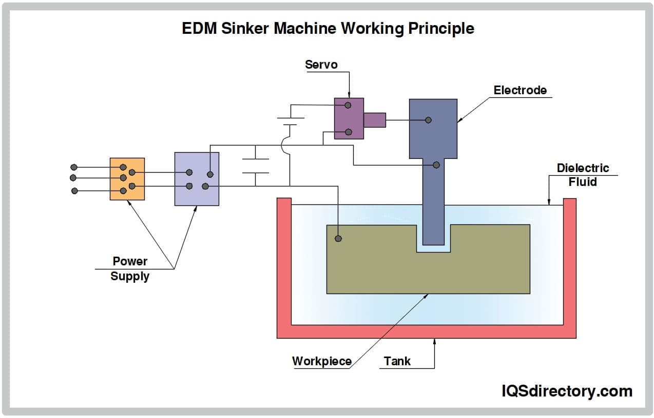
Sinker Electrical Discharge Machining (EDM) is a metal machining process used to create molds, dies, and parts using electrical sparks to erode material from a workpiece. It is preferred over other machining processes due to...
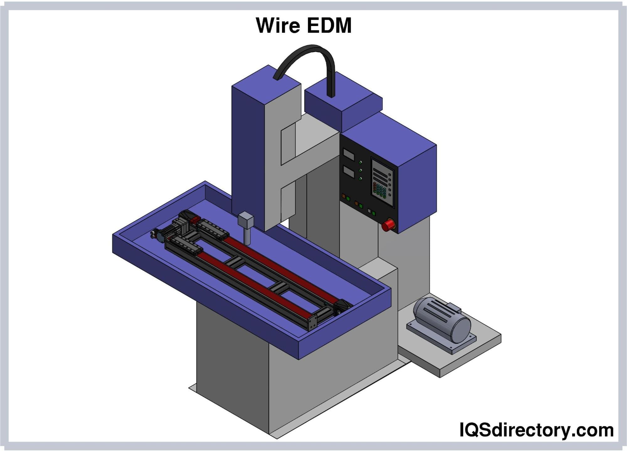
A method of precision machining called electrical discharge machining (EDM) removes material from a workpiece using thermal energy rather than mechanical force. A thin, single-strand metal wire and deionized water used to...
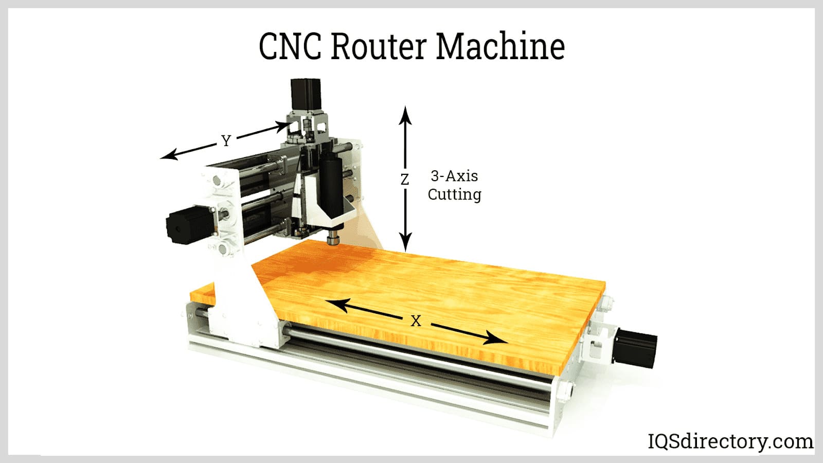
Machining is a manufacturing process used to produce products, parts, and designs by removing layers from a workpiece. There are several types of machining that include the use of a power driven set of machining tools to chip, cut, and grind to alter a workpiece to meet specific requirements...
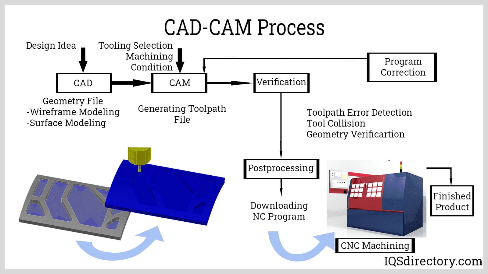
The CNC process, computer numerical control, is a method of manufacturing where programmed software directs the operation of factory tools and machinery. It is designed to manage a wide range of complex machines from grinders and lathes to mills and routers...