Gear Drive

Gear drives, sometimes referred to as gear trains and gearboxes, are mechanisms consisting of an assembly of gears, shafts, and other machine elements for mounting the rotating parts...
Please fill out the following form to submit a Request for Quote to any of the following companies listed on
This article takes an in depth look at gear reducers and their use.
You will learn more about topics such as:
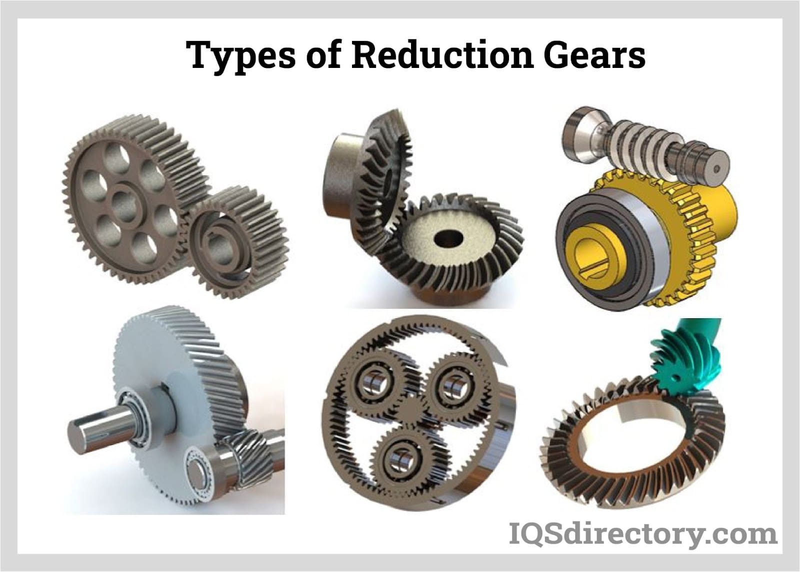
A gear reducer is a type of mechanical device engineered to diminish the speed of an input rotation while simultaneously amplifying the output torque. It accomplishes this through a sequence of interlocking gears, where a high-speed input shaft engages with a collection of gears to modify speed and torque. The specific configuration and number of gears in a gear reducer depend on the desired speed and torque characteristics tailored to the specific application being considered.
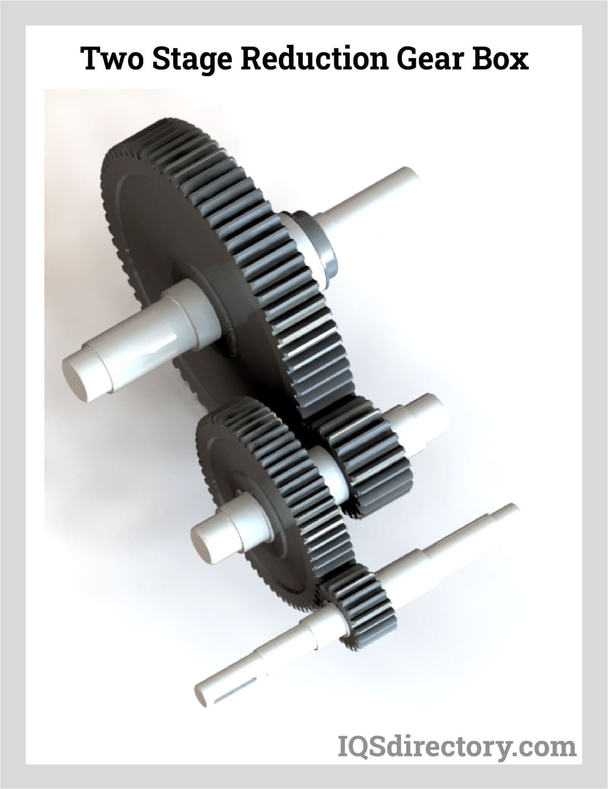
Gear reducers become essential when the driving gear is smaller in both size and number of teeth compared to the driven gear. This configuration contrasts with an overdrive arrangement, where the driving gear is comparatively larger and contains more teeth than the driven gear.
Gear reducers are indispensable in the automotive industry, particularly in vehicles such as cars and trucks. They modify the high-speed rotation generated by the engine into a slower-speed motion, enabling the tires to effectively utilize and manage the engine's power in a secure and efficient manner.
Gear reducers, also known as reduction gears or gearboxes, are critical mechanical components used in a wide range of industrial machinery. Their main function is to transform high-speed rotational energy from motors into lower, more manageable output speeds, while simultaneously increasing output torque. By adapting the speed-torque ratio, gear reducers enable machines to operate at optimal efficiency for specific applications, from conveyor belts and material handling systems to automation and robotics. Typically, a gear reducer is constructed with a larger gear (the driven gear) paired with a smaller gear (the drive gear), with both gears engaging and rotating together, forming the basis of a speed reduction mechanism.
In a basic gear reducer setup, when a larger gear drives a smaller gear, the smaller gear completes two revolutions for each revolution of the larger gear. Although this arrangement increases the output speed, it results in a decrease in torque. Conversely, when the smaller gear drives the larger gear, speed is reduced, and torque is increased, which is often the desired outcome in industrial drive systems requiring high force at reduced velocities.
The process of gear reduction is achieved through precise gear ratios that align the input and output speed and torque characteristics with the requirements of the driven application. Gear reducers modify the energy transfer between a prime mover (such as an electric motor) and the driven machinery by finely controlling the ratio between rotating gears, ensuring reliability and maximizing productivity across diverse sectors.
The gear ratio is a fundamental factor in gear reducer performance, quantifying how gears of different sizes interact to transfer rotary motion and mechanical energy. This ratio is primarily determined by comparing the number of teeth or the circumference of the drive gear to the driven gear. For instance, if a smaller gear completes two rotations for every single revolution of a larger gear, the gear ratio is 2:1—indicating the output speed is cut in half and output torque is doubled, assuming no significant power losses.
This example illustrates a vital concept that can be extended to more complex gear systems, known as compound gear trains or multi-stage gearboxes. These advanced assemblies often employ multiple gear pairs to incrementally convert high input revolutions per minute (RPM) into substantial output torque. For example, in a planetary gear reducer, the interaction of sun, planet, and ring gears achieves remarkably compact, high-torque solutions for automation and servo applications.
When calculating gear ratio, only the input (drive) gear and the output (driven) gear are considered; any intermediate idler gears do not affect the overall reduction ratio but may alter rotation direction. To determine the gear ratio, count the number of teeth on the drive gear and the driven gear. For example, if the drive gear has 7 teeth and the driven gear has 30 teeth, the drive gear must rotate approximately 4.3 times to make the driven gear complete one rotation. Selecting the ideal gear ratio is crucial for matching motor power outputs to specific application requirements—improving energy efficiency, motion control, and mechanical longevity.
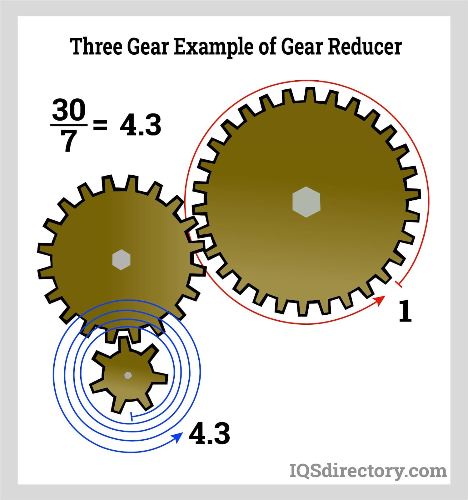
Torque refers to the rotational force that is input into a gear reducer and is subsequently converted into a different force and speed combination while generally maintaining the same power level. A gear reducer is engineered to multiply or decrease the torque delivered from a drive motor, directly proportional to a change in the number of output revolutions per minute (RPM). By selecting different gear stages and configurations—such as helical, spur, bevel, or worm gears—engineers can achieve the desired balance between speed and torque for different industrial applications, including packaging machinery, conveyors, and heavy-duty mining equipment.
Gear reducers play a crucial role in increasing or decreasing torque output, depending on their size and type. High-reduction gear sets are commonly used to amplify force for heavy loads, while low-reduction gearboxes enable higher speeds for precision applications. The gear ratio, determined by the relative sizes and teeth count of the gears, has a direct impact on the torque produced at the output shaft. This essential principle underpins the operation of all gearboxes, speed reducers, and industrial gears, safeguarding performance and extending component life by preventing overload on motors and mechanical systems.
Drive gears or gear drives are precisely engineered to change the speed, torque, or direction of a rotating shaft, playing an essential role in power transmission systems. In their simplest form, a small drive gear meshes with a larger gear connected to the output shaft, facilitating the required gear reduction. Drive gears are fundamental to providing variable output speed from a constant power source, adapting high-speed motors to the speed and torque demands of conveyors, mixers, and automated production lines.
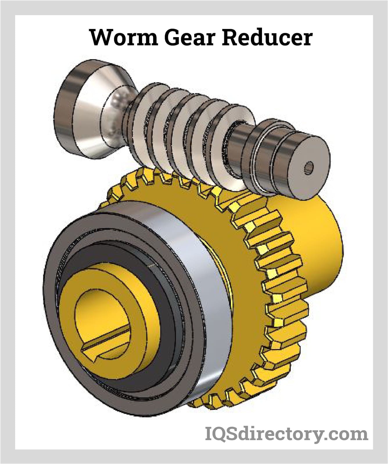
In the image below, the silver worm shaft functions as the drive gear in a two-stage worm gear reducer setup. The paired worm gear (worm wheel), shown in brass, engages with the worm shaft to deliver smooth, reliable power transmission across varying load conditions. Worm gear reducers are valued for their ability to provide high gear reduction ratios in a compact footprint and for their inherent non-reversibility, which adds a layer of safety and positional stability in lifts and hoists.
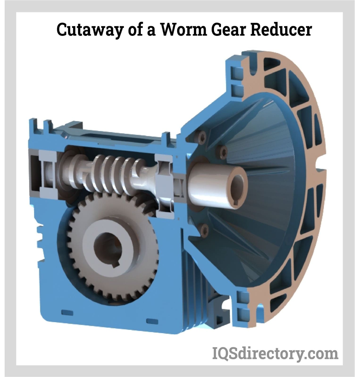
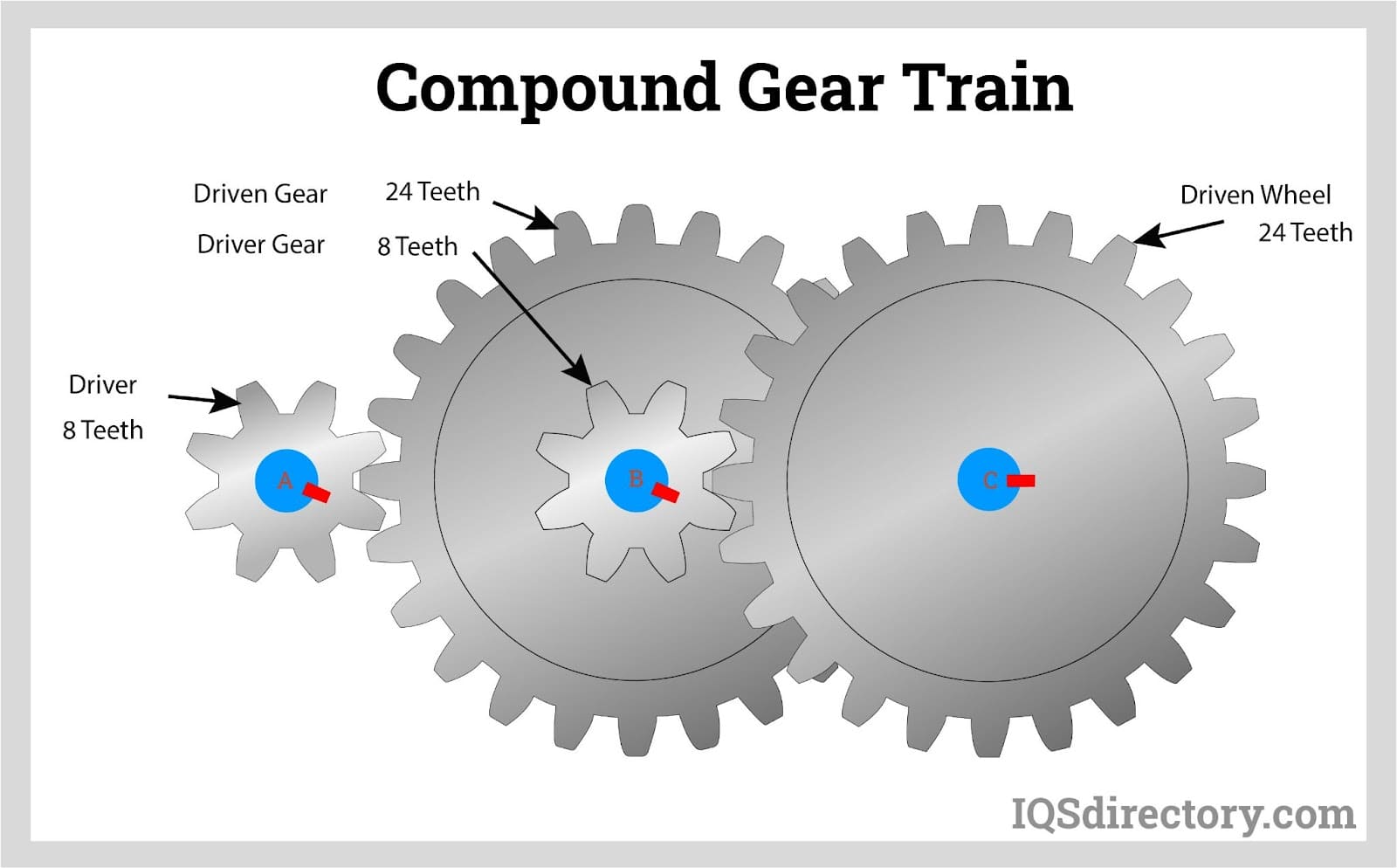
The driven gear is attached to the output shaft and transfers the modified torque and speed to the application. Typically, it is the larger gear in the drive set and may vary in design based on application requirements. Driven gears can take the form of helical gears for quieter operation, bevel gears for changing rotational axis, or planetary systems for high load capacity in compact spaces. In complex compound gear trains, such as the example below, two driven gears are linked to separate output shafts (shafts B and C). The gear ratio for the driven gear on shaft B is identical to that on shaft C, ensuring synchronized output—a crucial feature in many synchronized manufacturing processes.
Proper selection of the driven gear, as well as the gear material and tooth profile, directly affects reducer efficiency, wear resistance, and overall system reliability. Consulting with leading gear reducer manufacturers or experienced application engineers ensures that the chosen gear reducer matches the mechanical, operational, and environmental demands of each industrial project.
There are several common types of gear reducers utilized across industries, each providing unique advantages for specific applications. Helical gear reducers are known for quiet operation and high efficiency, making them ideal for precision machinery and automation systems. Worm gear reducers, as shown above, offer very high reduction ratios and are frequently used in conveyors, lifts, and heavy machinery. Planetary gear reducers deliver high torque density within a compact design and are widely implemented in robotics, motion control, and servo drive applications. Choosing the appropriate gear reducer type—based on required torque, speed, mounting orientation, and duty cycle—is critical to achieving optimal performance and reliability in your equipment.
When evaluating gear reducers for purchase or specification, important factors to consider include required output torque, desired speed reduction ratio, mounting style (such as foot-mounted or shaft-mounted), physical size constraints, and compatibility with the input power source (electric, hydraulic, or pneumatic motors). Also, take into account features such as backlash tolerance, efficiency ratings, lubrication type, and noise levels—ensuring the gear reducer matches the application's workload and environment. Leading manufacturers often provide detailed product datasheets and engineering support to help users select the most suitable speed reducer for their specific industrial or commercial application.
Investing in the correct gear reducer not only improves operational efficiency and equipment lifespan but also minimizes downtime, increases energy savings, and ensures seamless integration with existing drive systems.
A speed reducer, also known as a gear reducer or gearbox, is a mechanical device engineered to precisely adjust and control the rotational speed from an electric motor or other prime mover before it is transmitted to industrial equipment or machinery. By integrating a gear train comprised of various gear sets, a speed reducer efficiently lowers the high-speed rotation of the motor's shaft to a more manageable speed, resulting in significantly increased output torque. The gears inside a speed reducer typically have more teeth than the input (drive) gear, allowing the output (driven) gear to rotate at a slower rate while amplifying torque, making speed reducers essential in applications demanding high torque and controlled speed.
Installed between a power source—such as an AC or DC motor—and the machinery it drives, a speed reducer gearbox optimizes the motor's output to suit equipment requirements. Through a combination of specially designed large and small gears, speed reducers precisely lower input speed and deliver greater mechanical advantage in the form of torque multiplication. This ability to fine-tune speed and torque not only enables greater control over automation and manufacturing processes but also enhances system efficiency, extends equipment lifespan, and ensures safe operation. Today, industrial speed reducers are integral in robotics, conveyors, material handling, food processing, packaging equipment, and countless other driven applications.
Speed reducers—sometimes referred to as gear reducers or reduction gearboxes—come in four fundamental configurations: worm, planetary, spur, and bevel types, with options for single-stage or multiple-stage transmissions. Each configuration utilizes distinctive gear designs to provide specific speed reduction ratios and mechanical properties. Common variations by the shape of their gearing include cylindrical, bevel, helical, and cone-cylindrical gears. For further detail on types and applications, see our in-depth section on speed reducers.
When selecting a speed reducer for industrial or commercial use, it is important to consider key parameters such as gear ratio, rated torque, input speed, output speed, mounting style, and efficiency. Matching your application requirements with the correct type of gearbox can improve operational reliability, reduce energy consumption, and lower maintenance costs over time.
A worm speed reducer incorporates a worm wheel and worm shaft to achieve significant reduction ratios, commonly between 10:1 and 60:1. This right angle speed reducer design ensures perpendicular input and output shafts and is engineered for non-reversibility, providing intrinsic backdrive prevention and enhancing system safety and reliability. Worm gearboxes are favored for their quiet operation and shock-loading capability, making them ideal for conveyor systems, lifts, and heavy equipment where compactness and durability are critical.

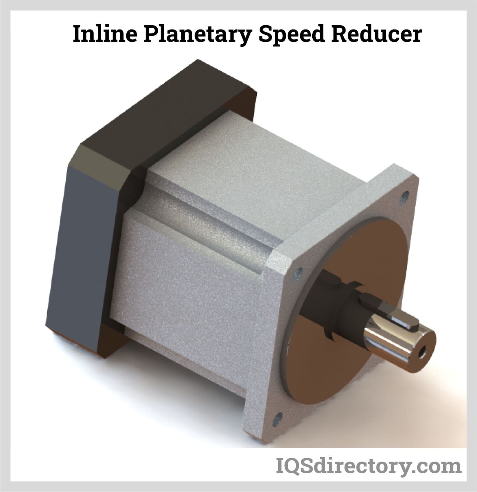
Planetary speed reducers or epicyclic gearboxes offer an array of advantages: compact and lightweight construction, low profile (ground clearance), exceptional transmission efficiency (often over 97% per stage), extended service life, and high output torque in a coaxial gear arrangement. These qualities enable planetary reducers to deliver high power density in space-constrained environments, commonly used in servo systems, robotics, precision automation, and mobile machinery. Their low backlash design and even torque distribution contribute to prolonged system life and consistent performance.
However, the advanced internal design of planetary gearboxes demands more specialized installation and proactive maintenance to maintain peak operational efficiency and prevent gear wear or misalignment. Regular lubrication checks and periodic inspection of gear teeth are recommended for maximizing longevity of planetary speed reducers in intense or continuous-duty applications.
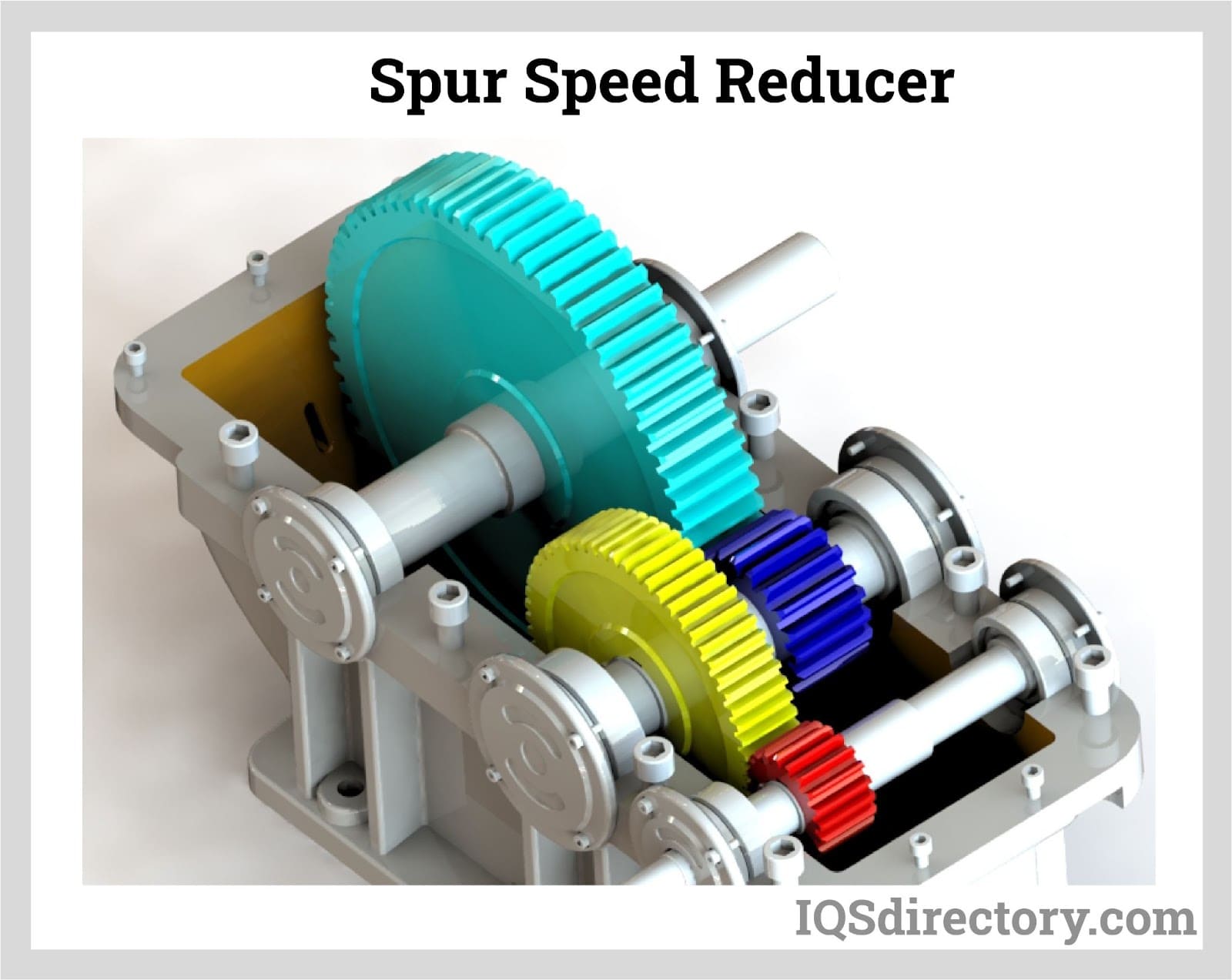
Spur speed reducers utilize parallel-axis, straight-toothed gears arranged in a simple, robust configuration. Their direct gear meshing achieves high mechanical efficiency and excellent torque output, making them suitable for high-speed, high-load applications. Spur gearboxes are among the most widely adopted types of speed reducers across manufacturing, processing, and power transmission sectors due to their straightforward design, reliability, and cost-effectiveness. They are commonly implemented in conveyor drives, mixers, and pump systems where consistent speed reduction and minimal maintenance are priorities.
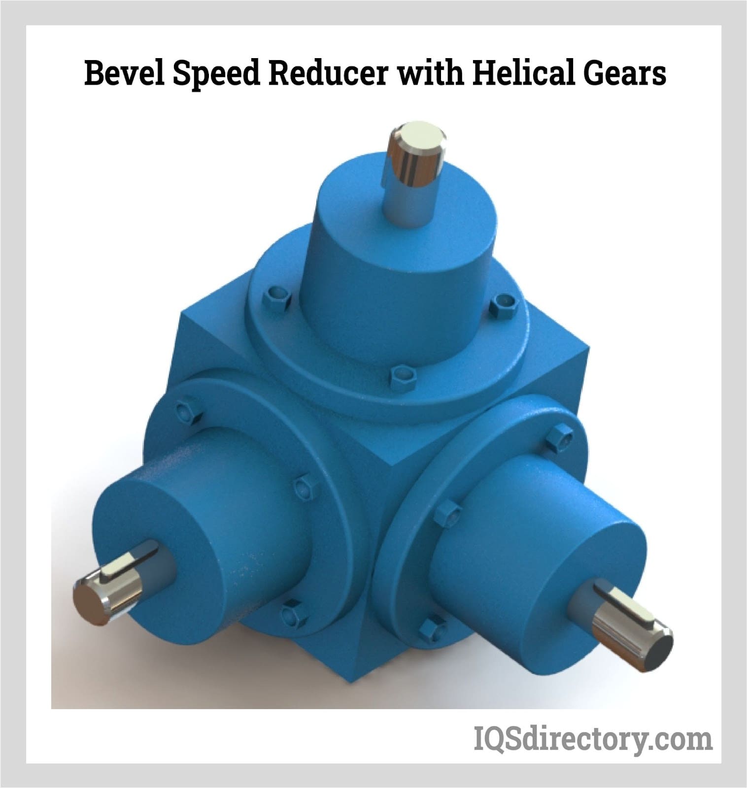
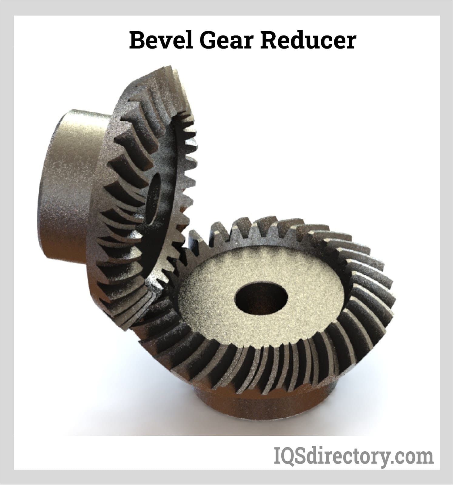
Bevel speed reducers are engineered for right angle drive applications requiring a low reduction ratio and efficient transfer of high torque loads. With angled gears—often conical or bevel in shape—this configuration enables users to redirect motion from one axis to another, such as changing rotational direction from lateral to longitudinal planes. Bevel gearboxes are especially valued in applications demanding reliable power transmission and compact installation profiles, such as machine tools, automotive systems, and conveyors. Enhanced performance can be achieved by integrating helical gears for quieter, more efficient operation and a higher gear meshing ratio. When selecting a bevel speed reducer, factors such as load capacity, ratio range, shaft orientation, and mounting options should be carefully assessed to ensure alignment with project requirements.
A gear reducer decreases the speed of an input rotation while increasing output torque, optimizing motor power for use in various machinery and industrial applications.
Gear ratio determines how input speed is reduced and torque is increased. A higher gear ratio cuts output speed but multiplies torque, directly impacting mechanical performance.
Common gear reducer types include helical, worm, planetary, and bevel. Each offers unique torque, efficiency, and design benefits for applications like conveyors, robotics, and lifts.
Consider required torque, speed reduction ratio, mounting style, size constraints, input power compatibility, efficiency, and noise. Match these to your application's operational needs.
Gear reducers in cars and trucks convert engine speed to usable torque, ensuring that tires can safely and efficiently manage engine power for effective vehicle movement.
Planetary speed reducers need regular lubrication checks and gear inspections to maximize operational efficiency, prevent gear wear, and ensure long service life in demanding applications.
A gear reducer is a device that adjusts rotational speed through the use of gears, shaft alignment, and gear configurations. It is commonly employed in reduction transmission systems where the drive motor is integrated with the gearbox or gear reducer.
Gear reducers can incorporate various types of gearboxes, including planetary, cylindrical, parallel shaft, worm, or screw types, each serving specific functions to meet application needs. Most gear reducers feature multiple gear series with varying gear ratios, which facilitate substantial gear reduction.
Bevel gear reducers feature an angled bell crank that enables the system's rotational direction to shift from transverse to longitudinal. They are designed to be compact yet capable of handling substantial power from three-phase asynchronous motors, synchronous motors, or asynchronous servo motors.
Similar to helical and hypoid gear reducers, bevel gear reducers operate with minimal noise while delivering high performance and exceptional energy efficiency.
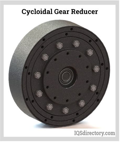
In a cycloidal gear reducer, the input shaft drives a bearing assembly that moves a cycloidal disc, which in turn is connected to an output shaft. The cycloidal disc's teeth mesh with a cam follower equipped with pin or needle bearings. This mechanism allows the output shaft to rotate at a significantly lower speed and with higher torque compared to the input shaft.
The primary advantage of cycloidal gear reducers is their ability to eliminate backlash, providing the precision and accuracy required for robotic applications and machine tools. Moreover, their rolling contact design results in reduced wear and increased durability.
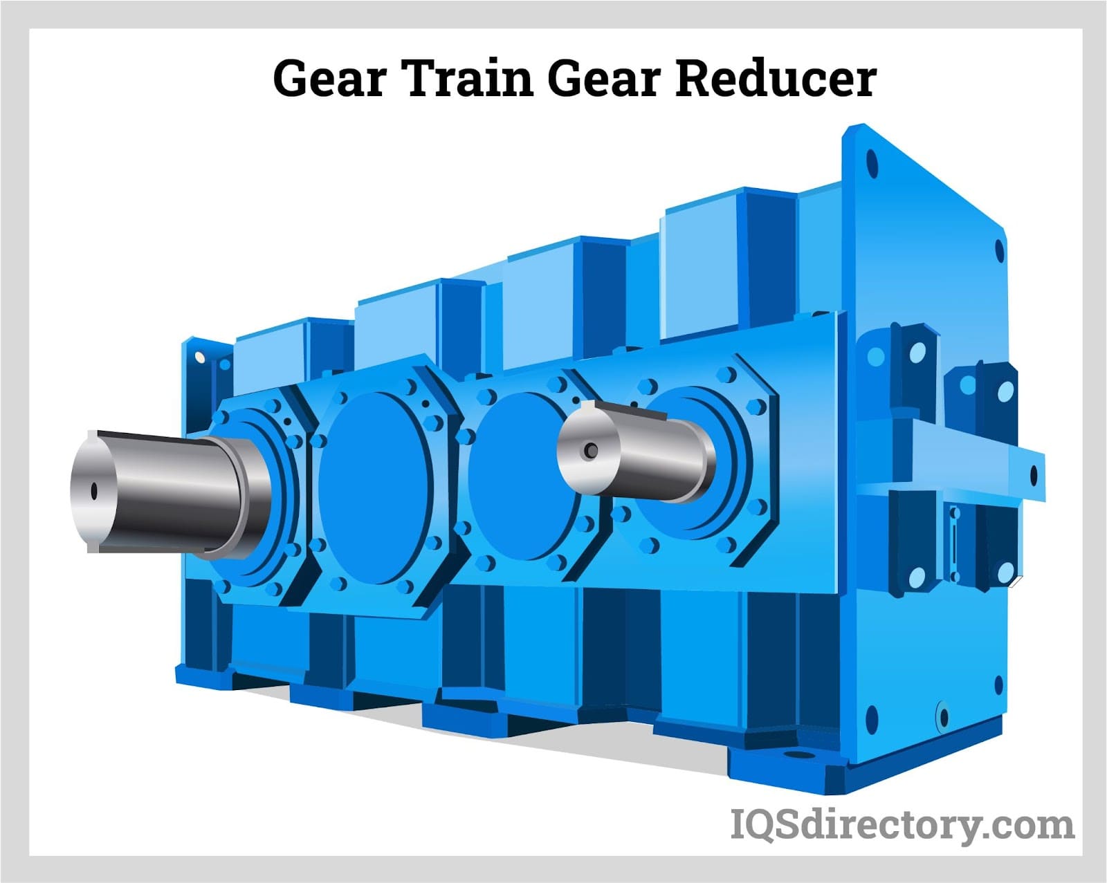
A gear train gear reducer consists of a sequence of gears that transmit power from an input shaft to an output shaft. These reducers are used in applications requiring substantial power and operate on parallel axes. The simplest configuration involves two gear trains: a drive gear and a driven gear. More complex versions include additional idler gears between the drive and driven gears to further refine the power transfer.
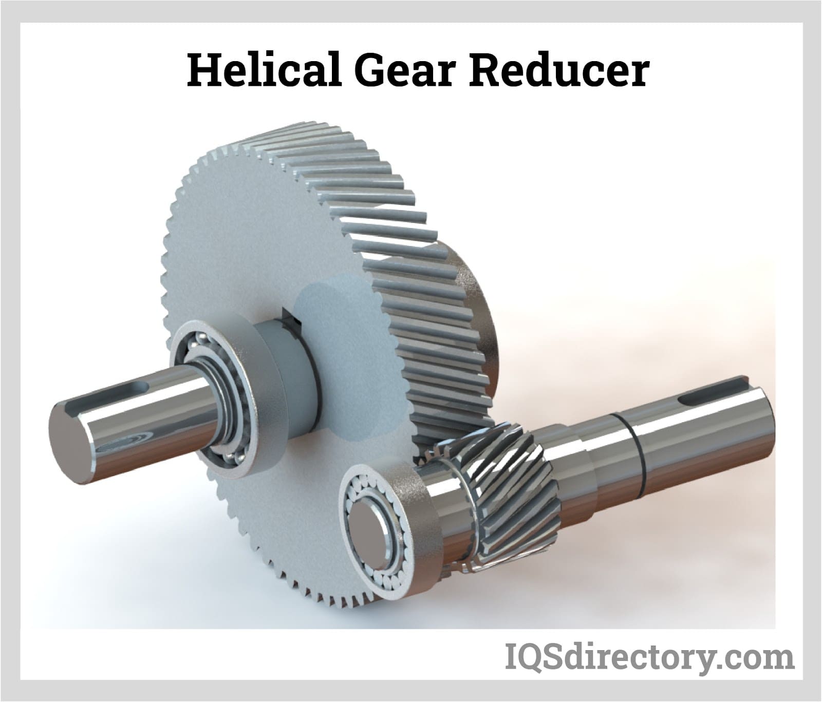
Helical gear reducers are compact and durable, designed to handle high overloads while saving space. They are ideal for applications requiring medium to high-speed operations. The helical gears feature slanted teeth, which enhance the meshing ratio, reduce noise, and increase strength. Their synchromesh design ensures continuous engagement and provides a larger contact area.
The angled teeth of helical gears allow for a longer tooth profile while maintaining the same number of teeth as a spur gear.
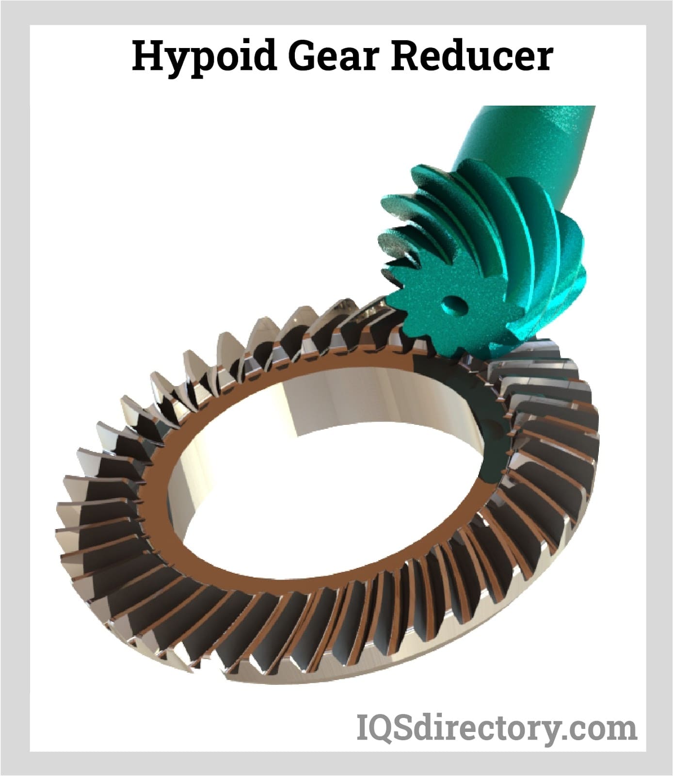
Hypoid gears are cone-shaped and used to transmit power between non-intersecting shafts. The offset between the smaller hypoid pinion and the larger hypoid gear allows them to mesh smoothly without interference. This design provides a large contact ratio, enabling the transmission of heavy loads with smooth operation and reduced noise, similar to helical gear reducers. Hypoid gear reducers are capable of achieving significant speed reductions.
Hypoid gears are commonly employed in applications where the shafts are at right angles and the distance between them is limited. They often serve as an intermediate solution between bevel and worm gears.
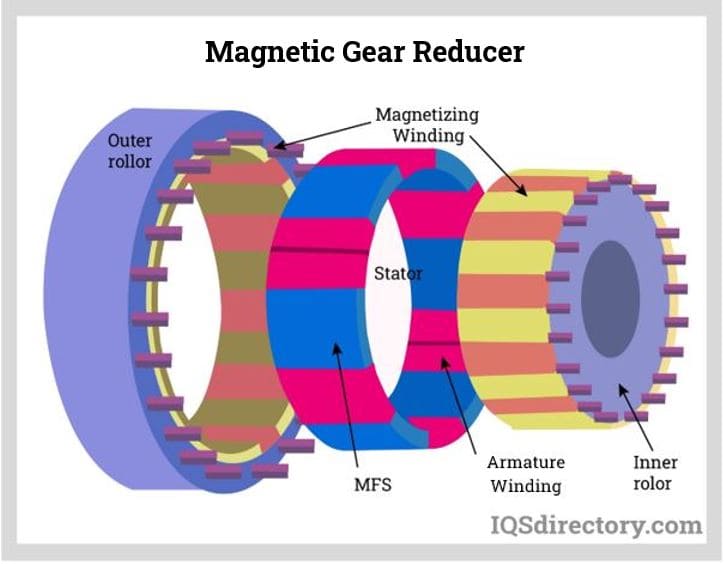
Magnetic gear reducers represent a distinctive type of gear reducer that operates using magnetic attraction rather than physical contact. Instead of gear teeth, they rely on opposing magnets that repel each other, allowing them to apply force at various angles without direct contact. This design eliminates wear and tear, as the gears do not physically touch each other.
Moreover, magnetic gears do not need lubrication or sealed barriers. They are typically constructed using permanent magnets or electromagnets, making them a low-maintenance and durable option.
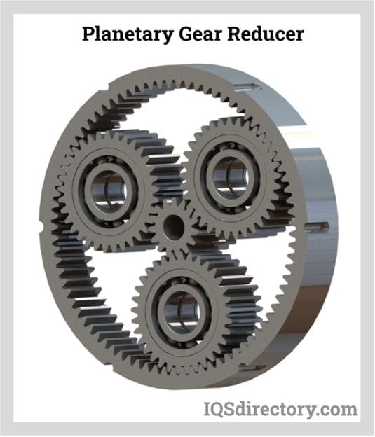
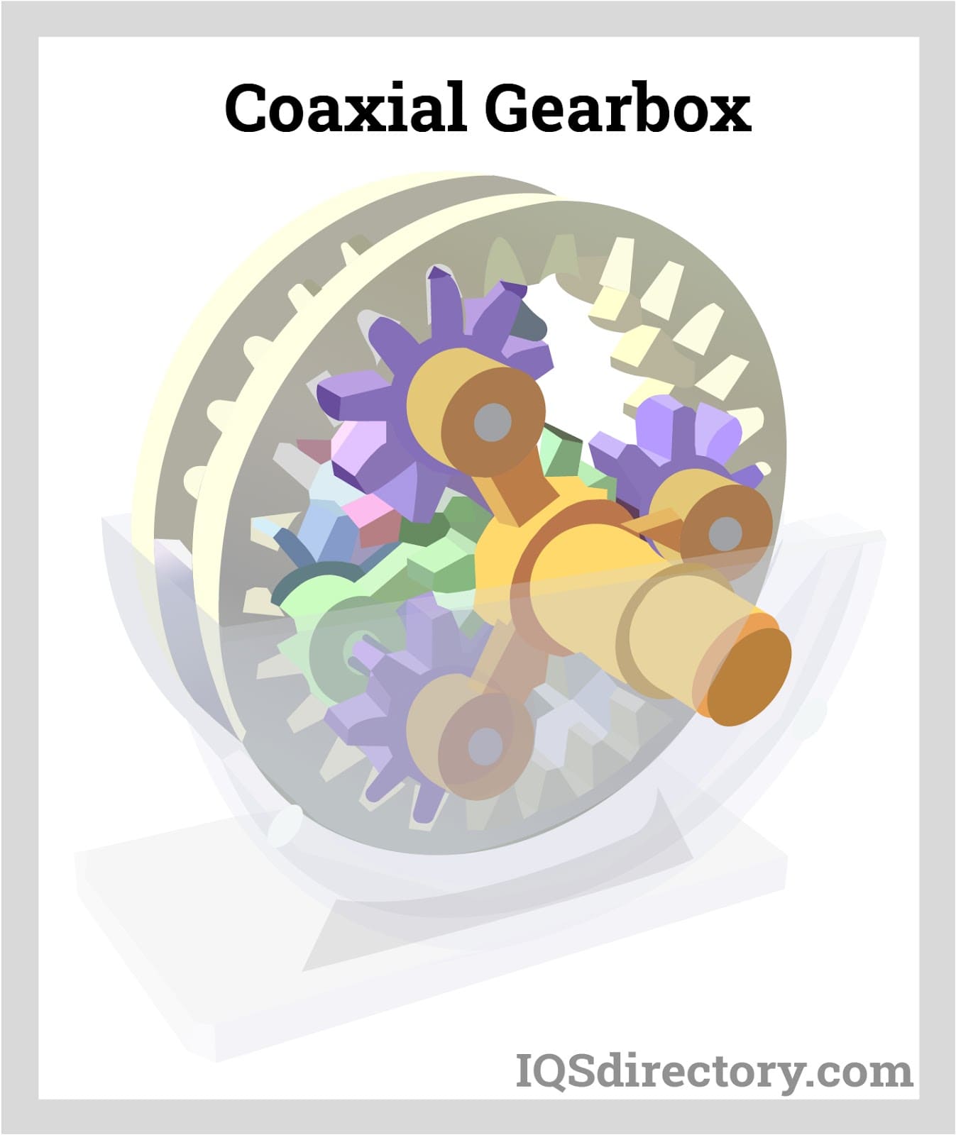
A planetary gear reducer consists of a central sun gear, orbiting planet gears, and a large ring gear. The planet gears are supported by the output shaft, the inner ring gear, and the sun gear. Power is transmitted through the sun gear at the center, which drives the planetary gears to rotate around the inner ring gear. This rotation of the planet gears then drives the output shaft, which delivers the output power.
A planetary reducer offers a long service life, compact size, high load capacity, low noise, high output torque, and excellent efficiency. It features power splitting and multiple tooth meshing, making it a highly versatile reducer suitable for various applications.
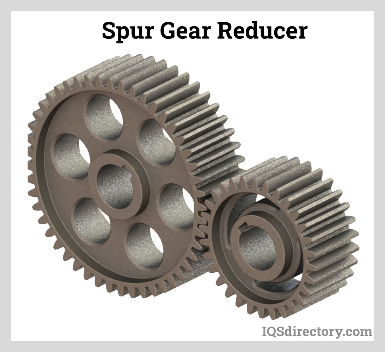
Spur gear reducers feature straight teeth that are aligned parallel to the axis. They are the most common type of gear reducer and can incorporate multiple gears with varying gear ratios. Spur gear gearboxes are known for their high efficiency, minimal backlash, and robust stability.
A worm gear reducer features a worm pinion input and an output worm gear arranged at a right angle. It converts the motor's high speed into a lower speed output with increased torque. Worm gear reducers are especially suited for space-saving applications due to their compact design and the small diameter of the output gear, while still providing excellent speed reduction in a compact package.
A coaxial axis gear reducer employs planetary gears that revolve around a central sun gear. Both the input and output gears are arranged concentrically, enhancing torque and efficiency. Typically, three to five planetary gears mesh with the internal gear, distributing power across multiple branches. The design aims for an even distribution of power.
The fundamental mounting options for gear reducers are base mounting and shaft mounting.
Gear reducers with orthogonal axes, such as bevel gear reducers, feature input and output shafts that are perpendicular to each other. While they are less precise than parallel axis gear reducers due to less optimal tooth contact, they are commonly used for power transmission and branching applications.

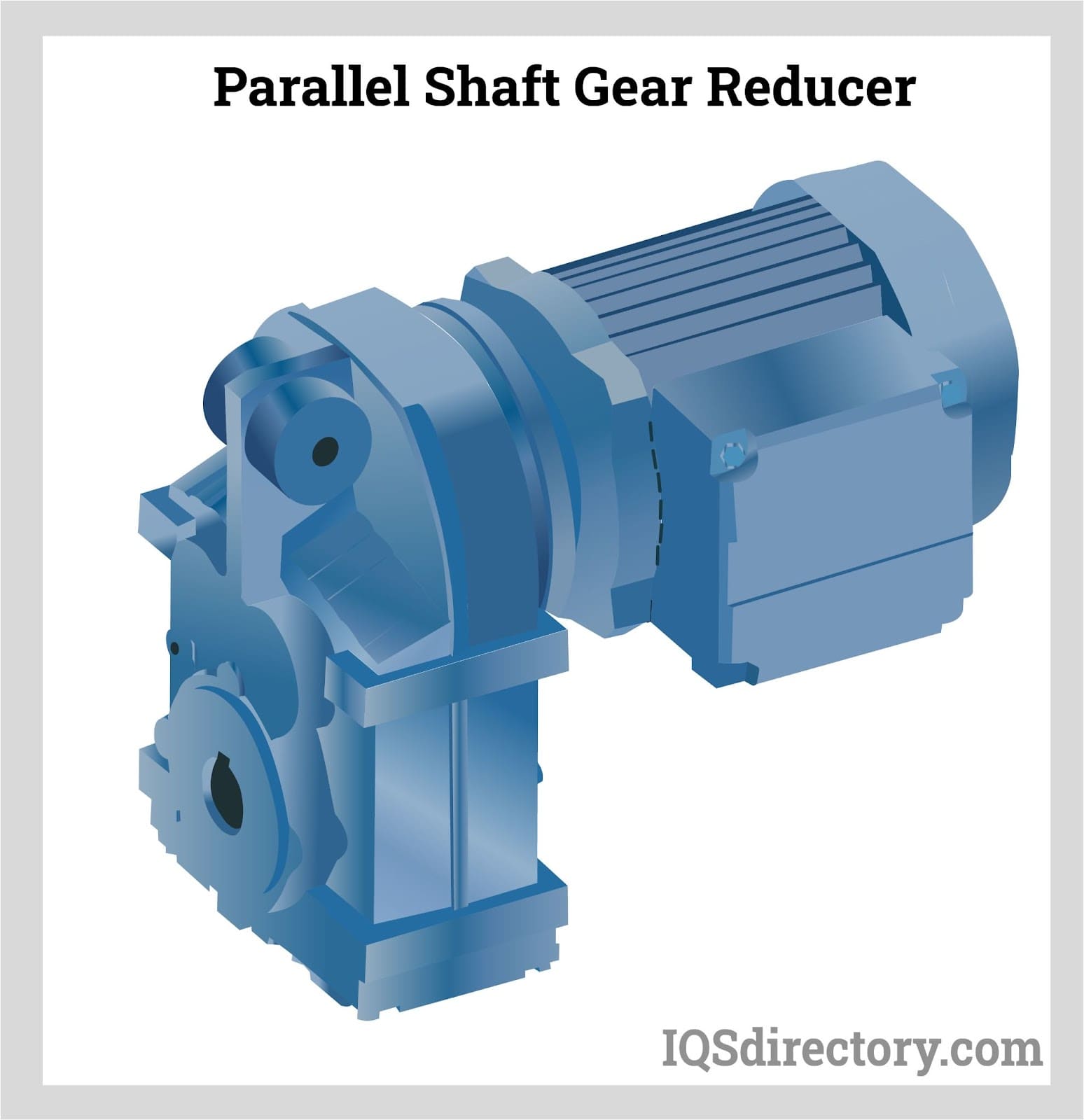
Parallel axes gear reducers have the output and input shafts parallel. They have very high precision and transmission efficiency. Parallel axes gear reducers can use large sized standard spur gears or helical gears. They are used in machines with high rotations on the load side, such as cranes, elevators, and conveyors.
When the input and output axes of a gear reducer are offset but orthogonal, it is known as a skew axes gear reducer. This design features non-intersecting, non-parallel axes with an offset gear centerline, leading to greater tooth surface contact and a higher contact ratio. Consequently, this results in increased torque capacity and smoother power transmission.
Before purchasing a gear reducer, several factors need to be considered. The primary role of a gear reducer is to adjust the torque and speed characteristics between the input and output shafts of a system. Understanding the application’s torque and rotational speed is therefore crucial.
A gear reducer enhances the torque from a motor and provides a new torque value for the application. Manufacturers indicate both maximum and minimum torque values in newton meters (Nm) for their products, with varying torque densities across different gear reducers.
Another key function of a gear reducer is to lower the motor speed, which is expressed as a reduction ratio. The motor’s rotational speed is adjusted by this ratio to achieve the desired output speed, typically measured in revolutions per minute.
At this stage of selection, it is crucial to consult with an expert, engineer, or designer familiar with gear reducers due to the variety of types available, each suited to different functions and specifications. The initial criteria involve determining the configuration of the input and output shafts.
Choosing the right dimensions for a gear reducer involves selecting the appropriate shaft type, such as orthogonal, coaxial, or parallel. Each shaft type has a specific orientation relative to the gear reducer—perpendicular, aligned, or parallel.
For applications subject to shock or cyclic loads, it is important to consider these conditions when selecting a gear reducer. This ensures that the gear reducer can handle increased torque effectively.
It is important to choose a gear reducer that operates efficiently to manage long-term costs effectively. Selecting the right gear reducer can offer significant benefits in terms of cost-efficiency over time.
Planetary gear reducers are suited for applications requiring rapid acceleration, low speeds, and high torque. They are commonly used in machine centers, machine tools, and agricultural machinery.
Worm gear gear reducers are used in applications with a high transmission ratio. They are less costly than other gear reducers and operate very quietly. Worm gear gear reducers are used on conveyors, winches, and material handling due to their non-reversibility.
Gear train reducers are designed for high-power applications and offer cost savings on maintenance due to their exceptional performance and low reduction ratio.
Bevel gear reducers allow for changes in rotational direction. They are compact, robust, and capable of handling substantial force. However, they may have lower performance, higher costs, and require frequent maintenance. They are typically found in farm equipment and heavy-duty conveyors.
Gear reducers play a crucial role in various machines and are essential for smooth operation. Proper selection of a gear reducer ensures the efficiency and effectiveness of a system. A knowledgeable manufacturer can provide guidance on the optimal solution for any application.
After selecting the appropriate gear reducer, maintaining a regular maintenance schedule is crucial for its effective and efficient operation. Regular upkeep is essential to prevent failures, errors, and reduced performance. Routine inspections help minimize or avoid potential issues.
Gear reducer manufacturers provide or recommend specific lubrication materials for their products. The lubricant must have the correct properties to optimize performance. During the break-in period, it may be necessary to filter the lubricant to remove contaminants. Regular checks on the lubricant’s quality and level are also important.
Only the lubricant should be present in a gear reducer. Contaminants such as dust and water, which can enter through faulty seals, can cause significant damage to the gears.
Gear reducers should be stored in clean, dry, and climate-controlled environments with all covers, vents, and drains securely closed. Even when not in operation, the lubrication cycle must be maintained, and the reducer should be rotated periodically to ensure even lubricant distribution.
Noise is often an early sign of problems with a gear reducer. Running the reducer without a load can help assess the issue. Persistent noise and vibration may indicate the need for an overhaul or replacement.
Overheating usually signals inadequate lubrication. Regularly checking the gear reducer's surface temperature can prevent overheating, which is often caused by friction due to insufficient lubricant.
Proper maintenance ensures the gear reducer's reliable operation for many years.

Gear drives, sometimes referred to as gear trains and gearboxes, are mechanisms consisting of an assembly of gears, shafts, and other machine elements for mounting the rotating parts...
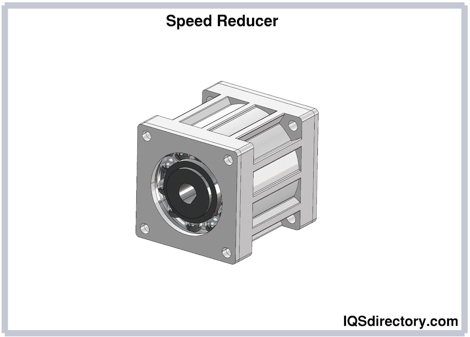
A speed reducer is a gear train between the motor and the machinery that is used to slow down the transmission of power. Speed reducers, also known as gear reducers, are mechanical devices that serve two roles...
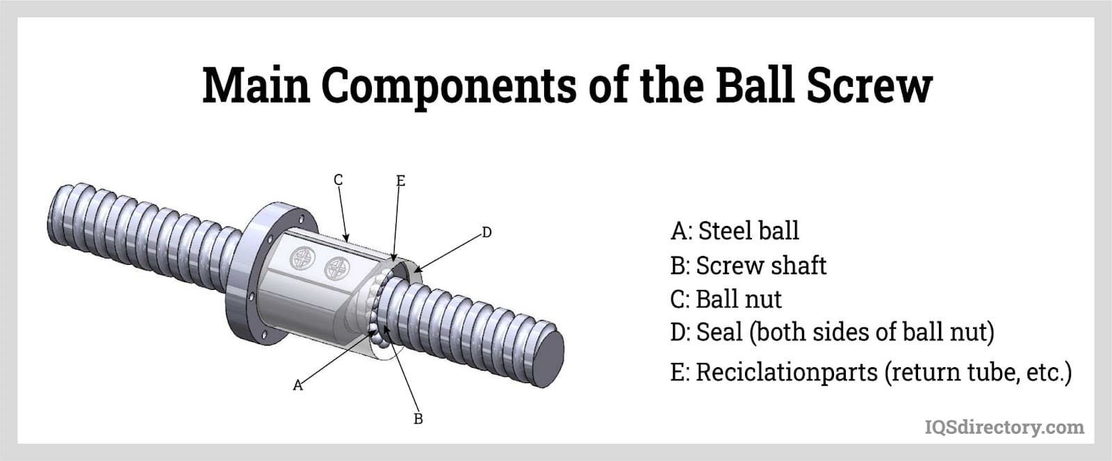
Ball screws are mechanical linear actuators that consist of a screw shaft and a nut that contain a ball that rolls between their matching helical grooves. The primary function of ball screws is to convert rotational motion to linear motion. Ball nuts are used in...
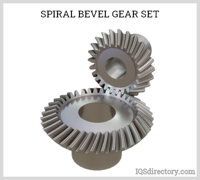
A bevel gear is a toothed rotating machine element used to transfer mechanical energy or shaft power between shafts that are intersecting, either perpendicular or at an angle. This results in a change in the axis of rotation of the shaft power...
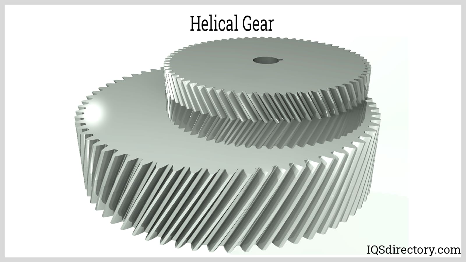
A gear is a particular kind of simple machine that controls the strength or direction of a force. A gear train is made up of multiple gears that are combined and connected by their teeth. These gear trains allow energy to move from...
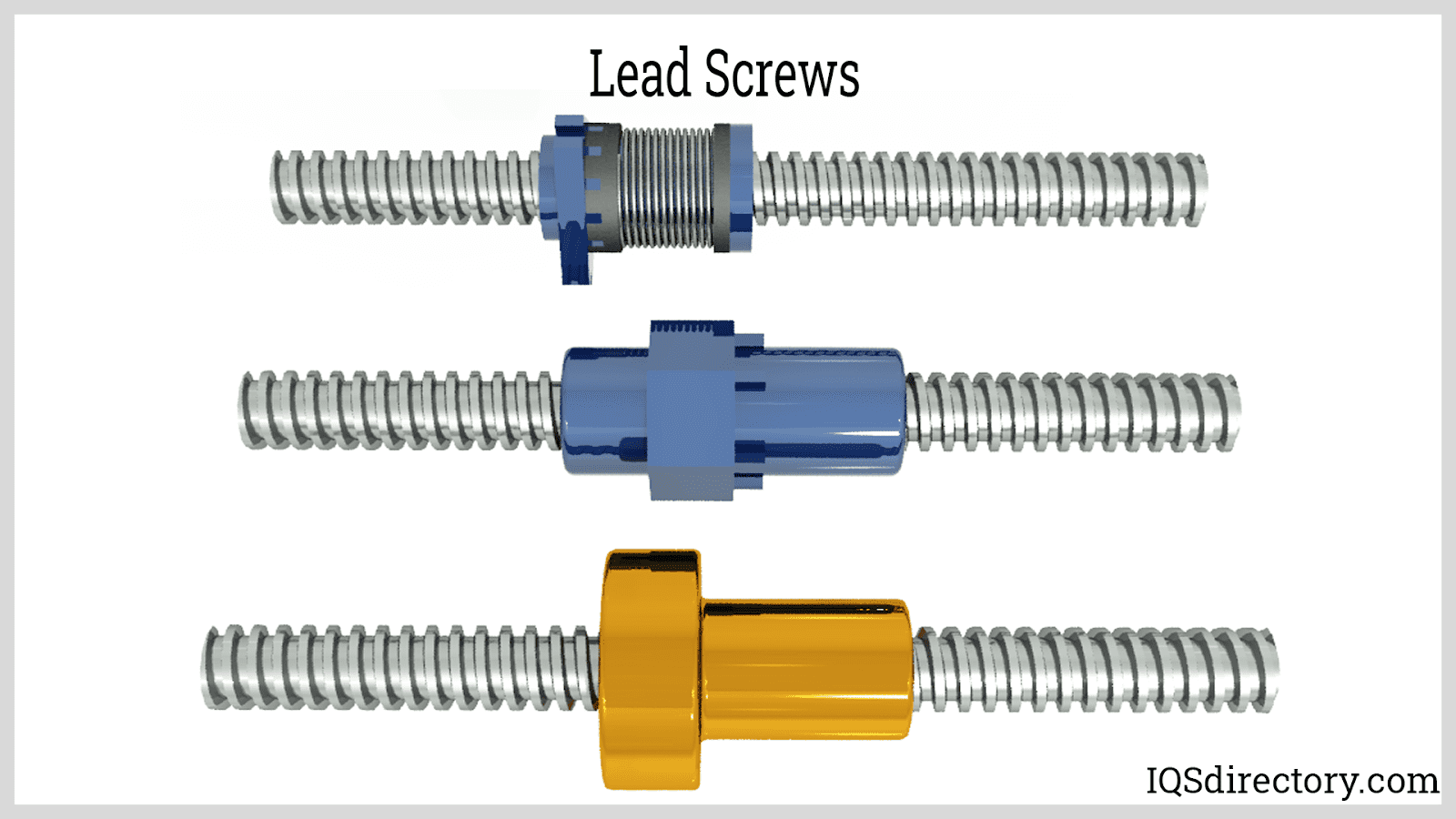
A lead screw is a kind of mechanical linear actuator that converts rotational motion into linear motion. Its operation relies on the sliding of the screw shaft and the nut threads with no ball bearings between them. The screw shaft and the nut are directly moving against each other on...
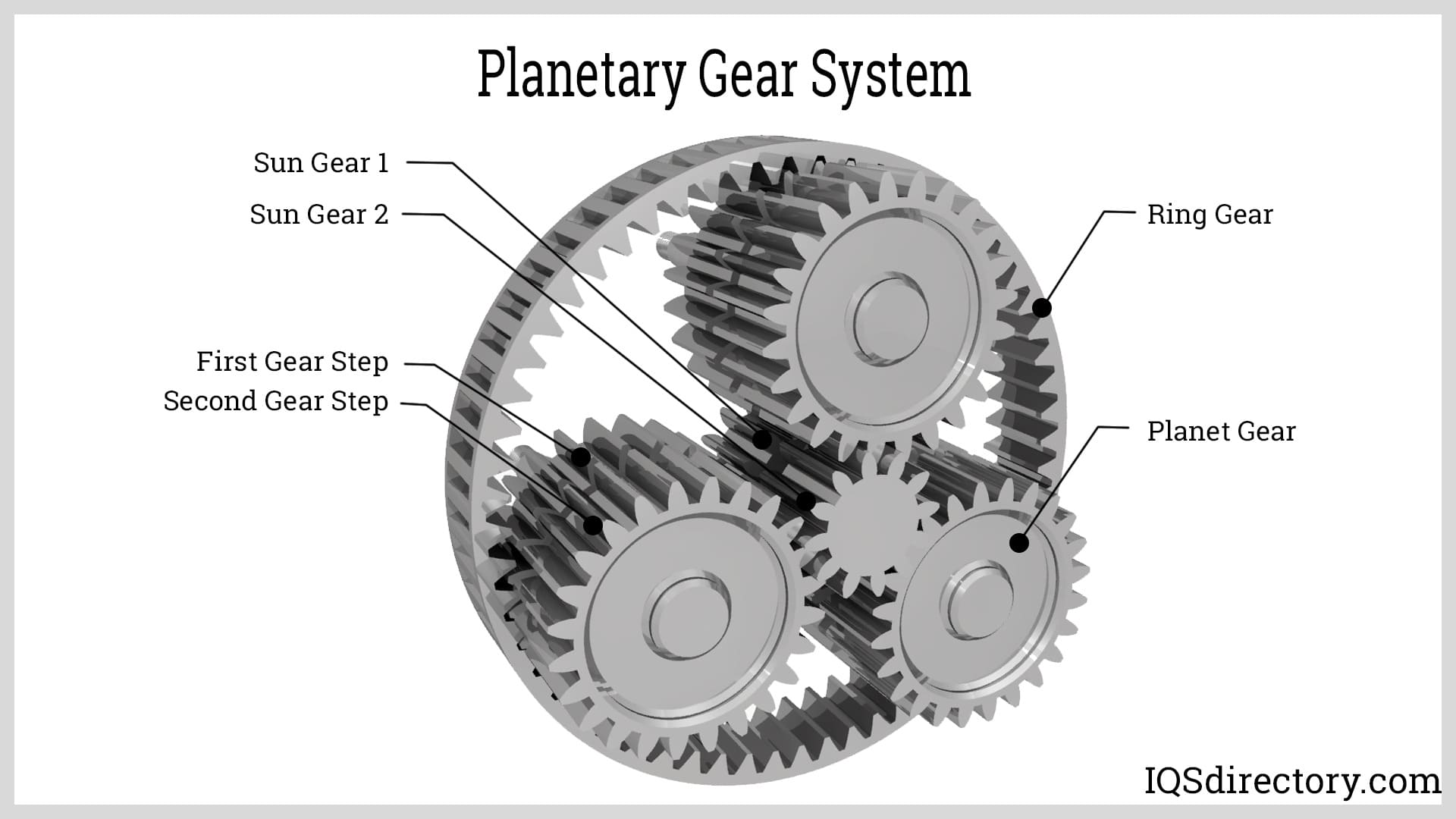
A planetary gear is an epicyclic gear that consists of a central gear, referred to as the sun gear and serves as the input gear, which has three or more gears that rotate around it that are referred to as planets...
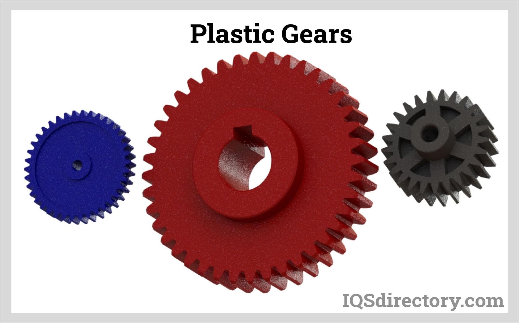
A plastic gear is a toothed wheel made up of engineering plastic materials that work with others to alter the relation between the speed of an engine and the speed of the driven parts. The engineering plastic materials used in manufacturing plastic gears can be...
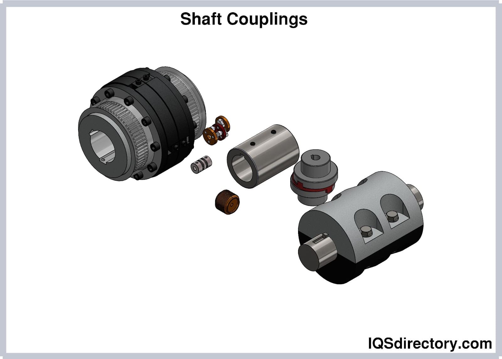
Shaft couplings are devices that connect two shafts to transmit power from the driveshaft to the driven shaft while absorbing some degrees of misalignments and mounting errors between the two shafts...
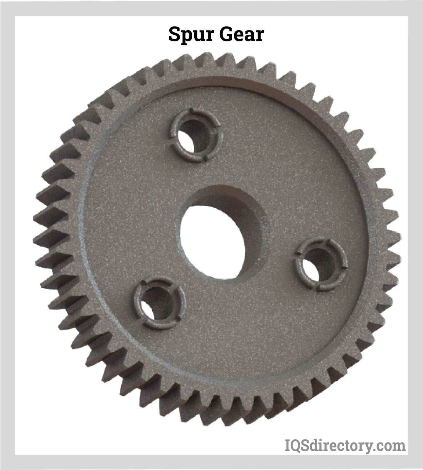
A spur gear is a cylindrical toothed gear with teeth that are parallel to the shaft and is used to transfer mechanical motion and control speed, power, and torque between shafts. They are the most popular types of cylindrical gears and...
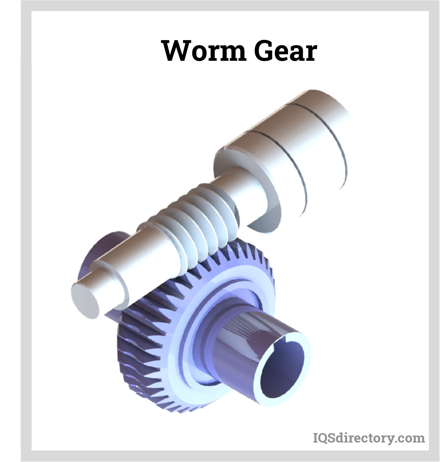
A worm gear is a staggered shaft gear that creates motion between shafts using threads that are cut into a cylindrical bar to provide speed reduction. The combination of a worm wheel and worm are the components of a worm gear...
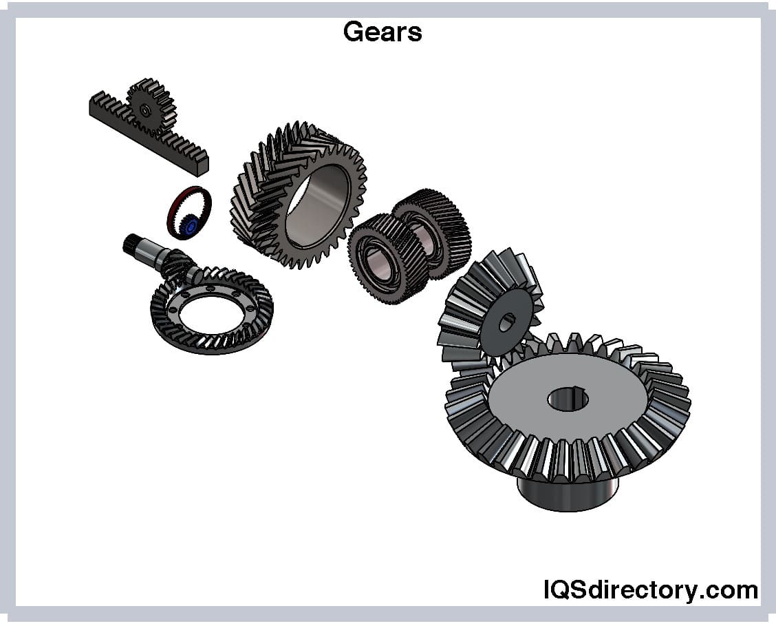
A rotary circular machine with a tooth in its structure and is used to transfer torque and speed from one shaft to another is called a gear. Gears are also known as cogs and have cut teeth in the cogwheel or gear wheel...